
Flanges are the unsung heroes of modern piping systems. From oil pipelines running hundreds of miles to the water lines in an industrial plant, flanges make the connection possible. They ensure that pipes, valves, and pumps can be assembled securely, inspected when needed, and replaced without tearing down the entire system.
But here’s the challenge: flanges come in dozens of sizes, standards, and pressure ratings. Using the wrong flange can lead to leaks, equipment failure, or even accidents in high-pressure systems. That’s where a flange size chart comes in — it provides the exact measurements engineers and technicians need to pick the right flange.
This article is a comprehensive guide to flange sizes. We will break down what flanges are, the different types, international standards, pressure classes, materials, and provide you with a detailed flange size chart for reference.
What is a Flange?
A flange is a disc-like mechanical component used to connect pipes, valves, pumps, or other equipment. Instead of welding everything permanently, flanges allow sections of a piping system to be bolted together. A gasket is placed between the flange faces to prevent leaks.
Think of a flange as the “connector piece” in a Lego set. Just as Lego pieces snap together in different sizes and shapes, flanges bolt together pipes of various sizes, allowing flexibility in design and maintenance.
Why are flanges important?
They allow for easy disassembly when cleaning or inspecting the system.
They provide a strong, leak-proof seal with gaskets.
They help connect different types of equipment like valves, pumps, and strainers.
They can handle high pressure and temperature conditions when made from the right materials.
Without flanges, piping systems would be much harder to build and maintain.
Types of Flanges
Different applications require different flange designs. Here’s a closer look at the main types of flanges used in industries:
1. Weld Neck Flange
Has a long tapered hub that is welded to the pipe.
Reduces stress concentration, making it ideal for high-pressure, high-temperature applications such as steam plants or oil refineries.
Provides excellent durability, though it is more expensive than other types.
2. Slip-On Flange
Simply slips over the pipe and is welded on both sides.
Quick to install and requires less accuracy in cutting the pipe length.
Best suited for low-pressure systems such as water lines or fire protection systems.
3. Socket Weld Flange
Pipe is inserted into a socket and welded.
Strong and reliable, commonly used for small-diameter, high-pressure pipelines.
Popular in chemical processing plants.
4. Blind Flange
A solid plate with bolt holes, used to seal off the end of a pipe.
Very useful for system testing, maintenance, or future pipeline extensions.
For example, a blind flange is often installed at the end of a refinery pipeline for future connection.
5. Lap Joint Flange
Always used with a stub end, which allows the pipe to rotate inside the flange.
Ideal for systems requiring frequent dismantling, such as food processing plants where cleaning is routine.
Cost-effective when made from carbon steel while using a corrosion-resistant stub end.
6. Threaded Flange
Screwed directly onto pipes with external threads, no welding required.
Common in low-pressure, non-critical systems, such as plumbing or compressed air lines.
7. Orifice Flange
Designed with holes to measure the flow of liquids or gases.
Widely used in flow measurement systems in power generation and oil industries.
Each type serves a unique purpose, so understanding their characteristics helps in selecting the right one for the job.
Flange Standards
Flanges are not universal — their dimensions and ratings depend on international standards. Choosing the wrong standard can make two flanges incompatible, even if they appear similar.
The Main Standards for Flanges
ASME/ANSI (USA) – Most widely used around the world. Standards like ASME B16.5 define dimensions and pressure ratings.
DIN (Germany/Europe) – Common in European industries. Known for high precision.
JIS (Japan) – Used extensively in Asian industries, particularly in shipbuilding and manufacturing.
BS (British Standard) – Traditional standard used in the UK.
EN (European Norm) – Harmonized standards for the European Union, replacing many national standards.
For example, a 2-inch ASME flange might not match a 2-inch DIN flange because their bolt patterns and diameters differ. That’s why engineers must always confirm the standard being used in a project.
Pressure Ratings of Flanges
Flanges are designed for specific pressure and temperature limits. In ASME standards, flange pressure classes are labeled as:
Class 150 – Low pressure, general-purpose piping.
Class 300–600 – Medium pressure, often used in chemical and refinery industries.
Class 900–1500 – High pressure, suitable for power plants.
Class 2500 – Extremely high-pressure systems, such as nuclear plants.
Example: If you are connecting a steam line in a refinery operating at 600 psi, you cannot use a Class 150 flange. You’ll need a higher class such as 600 or 900, depending on the design temperature.
🌟 Our readers also liked 👉 Drill Chart: Complete Guide
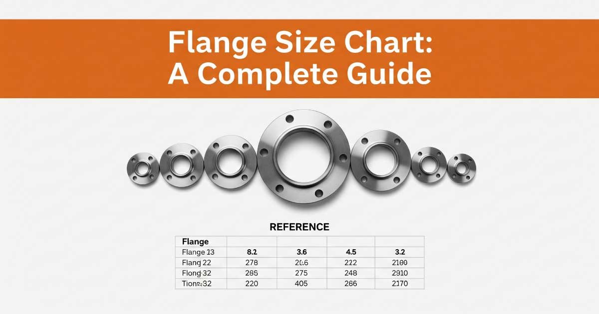
Flange Size Chart (ASME B16.5 – Class 150 Example)
Below is a detailed flange size chart showing common dimensions.
| Nominal Pipe Size (NPS) | Flange Outside Diameter (mm) | Bolt Circle Diameter (mm) | Number of Bolts | Bolt Hole Diameter (mm) |
|---|---|---|---|---|
| 1/2″ (DN 15) | 90 | 60.3 | 4 | 15.9 |
| 3/4″ (DN 20) | 100 | 69.9 | 4 | 15.9 |
| 1″ (DN 25) | 110 | 79.4 | 4 | 15.9 |
| 1 1/2″ (DN 40) | 125 | 98.4 | 4 | 15.9 |
| 2″ (DN 50) | 150 | 120.7 | 4 | 19.1 |
| 3″ (DN 80) | 190 | 152.4 | 4 | 19.1 |
| 4″ (DN 100) | 230 | 190.5 | 8 | 19.1 |
| 6″ (DN 150) | 280 | 241.3 | 8 | 22.2 |
| 8″ (DN 200) | 345 | 298.5 | 8 | 22.2 |
| 10″ (DN 250) | 405 | 362.0 | 12 | 25.4 |
| 12″ (DN 300) | 485 | 431.8 | 12 | 25.4 |
This table is based on Class 150 flanges. For higher pressure classes, the outside diameter and bolt circle will increase to handle the stress.
Flange Size Chart PDF
Download our Flange Size Chart PDF for quick access to detailed flange dimensions, including outside diameters, bolt circles, bolt counts, and hole sizes. Designed in landscape view for clarity, this chart follows ASME B16.5 Class 150 standards. A handy reference for engineers, technicians, and students working on piping projects and industrial system design.
Materials Used for Flanges
Flanges must withstand the medium flowing inside the pipes — whether it’s water, oil, chemicals, or steam. The right material ensures strength, safety, and durability.
Carbon Steel – Strong, affordable, used in most general industries.
Stainless Steel – Resistant to corrosion, perfect for food processing, pharmaceuticals, and chemical plants.
Alloy Steel – Designed to resist high temperatures and pressure; used in power plants.
Cast Iron – Cheap but brittle, used in older water lines.
PVC/Plastic Flanges – Lightweight and corrosion-resistant, suitable for low-pressure water systems.
Example: In a chemical plant handling acids, stainless steel flanges are preferred over carbon steel to avoid corrosion.
Applications of Flanges
Flanges are everywhere — from small water systems to massive offshore rigs.
Oil and Gas Industry – Weld neck and blind flanges are used in pipelines and refineries.
Chemical Plants – Corrosion-resistant flanges (stainless steel) ensure safety.
Power Plants – High-pressure flanges connect steam lines and turbines.
Shipbuilding – JIS flanges are widely used in marine systems.
Water Distribution – Slip-on flanges are used for easy assembly and repair.
A real-world example: In offshore drilling platforms, flanges must withstand not just high pressure but also saltwater corrosion. That’s why duplex stainless steel flanges are common in such environments.
🌟 Our readers also liked 👉 Drill Tap Chart: Complete Guide
How to Select the Right Flange Size
Choosing the correct flange goes beyond just matching pipe size. Here are the key factors:
Pipe Size (NPS/DN) – Match the nominal pipe size for proper fit.
Pressure Rating – Ensure the flange can handle the system’s maximum pressure.
Material Selection – Pick materials based on fluid type, temperature, and environment.
Flange Standard – Always confirm whether the system uses ASME, DIN, JIS, or another standard.
Type of Flange – Choose weld neck, slip-on, or lap joint based on installation and maintenance needs.
Gasket Compatibility – Ensure the flange face matches the gasket type (raised face, flat face, or ring joint).
By following these guidelines, engineers avoid costly mismatches and potential system failures.
Conclusion
A flange size chart is more than just a reference table — it’s a safety tool. Using the wrong size or class of flange can compromise the entire piping system.
This guide covered:
What flanges are and why they matter
Types of flanges and their uses
Global flange standards (ASME, DIN, JIS, EN)
Pressure ratings and how they affect design
A detailed flange size chart for Class 150 flanges
Materials and applications across industries
Whether you are designing a refinery pipeline, a power plant, or a simple water supply system, selecting the right flange ensures efficiency, reliability, and safety. Always consult the proper standards and refer to a flange size chart before making your selection.
🌟 Our readers also liked 👉 Bolt Size Chart: A Complete Guide
FAQs:
What is the purpose of a flange size chart?
A flange size chart provides accurate measurements for pipe flanges, including bolt circle, diameter, and bolt hole size. Engineers and technicians rely on it to ensure proper connections in piping systems. Without the chart, mismatches can occur, leading to leaks, equipment failure, or costly downtime in industrial operations and maintenance.
How do I select the right flange for my project?
Choosing the right flange requires checking pipe size, pressure rating, flange standard, and material. A flange size chart helps confirm dimensions and bolt patterns for compatibility. Engineers also consider fluid type, temperature, and maintenance needs. Correct selection ensures safe, leak-proof joints and reduces risks in critical systems like oil, gas, and power plants.
What are the most common flange standards?
The most widely used standards include ASME/ANSI (USA), DIN (Germany/Europe), JIS (Japan), BS (British Standard), and EN (European Norm). Each has different dimensions and bolt patterns. Engineers must verify which standard is specified for the project. A flange size chart designed for the right standard ensures accurate selection and smooth integration into piping systems.
Why are pressure classes important in flanges?
Pressure classes define how much pressure a flange can safely handle. For example, ASME Class 150 is used for low-pressure systems, while Class 600 or higher is for high-pressure operations. Selecting the wrong class can cause joint failure. A flange size chart helps identify flange dimensions that match the required pressure class and system safety.
Which materials are best for flange manufacturing?
Flanges are made from carbon steel, stainless steel, alloy steel, cast iron, or PVC. The choice depends on the system’s pressure, temperature, and fluid type. Stainless steel is ideal for corrosion resistance, while carbon steel is affordable for general use. The flange size chart ensures correct sizing, while the right material ensures durability and safety.
Can I use the same flange chart for all pressure ratings?
No, flange charts differ across pressure classes. A Class 150 flange has smaller dimensions compared to Class 600 or 900, even if the pipe size is the same. Each chart corresponds to specific standards and pressure ratings. Using the correct flange size chart ensures accuracy, prevents mismatches, and guarantees reliable, leak-free piping connections.