
When it comes to transmitting torque in mechanical systems, not every application can rely on keyways or friction fits alone. For high-strength, high-precision, and long-lasting connections, spline shafts are the preferred choice. They may look like a simple shaft with ridges, but these ridges — called splines — play a crucial role in connecting rotating components like gears, couplings, and hubs.
Whether you’re working in automotive, aerospace, robotics, or heavy machinery, knowing the correct spline shaft size chart is essential. This chart acts as a blueprint for machinists and engineers, ensuring proper fits, efficient torque transfer, and reliable performance.
In this guide, we’ll explore what spline shafts are, their types, how they are measured, why size standards matter, and finally, provide a detailed spline shaft size chart for reference.
What is a Spline Shaft?
A spline shaft is a cylindrical shaft with a series of longitudinal ridges (splines) cut into it. These splines fit into matching grooves in a mating hub or gear, locking the two together so that torque is transmitted without slippage.
If a keyway uses a single groove to lock components, a spline shaft takes it to the next level — using multiple grooves for a stronger, more balanced connection.
For example, in an automobile transmission system, spline shafts are used to connect gears and clutches. This ensures the power from the engine is transmitted smoothly to the wheels, even under high loads.
Why Use Spline Shafts Instead of Keyways?
While both serve a similar purpose (torque transmission), spline shafts offer several advantages:
Stronger Connection: Multiple splines share the load, reducing stress on any single point.
Better Alignment: Provides precise positioning between shaft and hub.
High Torque Capacity: Can handle heavier loads compared to a single keyway.
Durability: Reduced wear due to distributed force.
Smooth Sliding Motion: Some splines allow components (like gears) to slide along the shaft while still transmitting torque.
This is why spline shafts are commonly found in gearboxes, automotive axles, turbine engines, agricultural equipment, and industrial robots.
Types of Spline Shafts
Not all splines are the same. They differ based on shape, purpose, and manufacturing method. The most common types include:
Involute Splines
Teeth shaped like an involute curve (same as gears).
Provides smooth engagement and disengagement.
Common in automotive gear systems.
Straight-Sided Splines
Teeth have straight sides.
Simpler to manufacture.
Often used in industrial applications.
Serrations (or Serrated Splines)
Similar to fine splines with shallow teeth.
Used in light-duty precision applications.
Helical Splines
Teeth are cut at an angle (helical form).
Allow axial movement under rotation (like a screw).
Internal and External Splines
External splines = on the shaft.
Internal splines = inside the hub.
They always work together as a pair.
How to Measure a Spline Shaft
Measuring spline shafts requires careful inspection. Here’s what to check:
Number of Splines (Teeth)
Count the ridges along the shaft circumference.
Major Diameter
Outside diameter across the tips of splines.
Minor Diameter
Diameter measured across the base (roots) of the splines.
Pitch Diameter
Theoretical diameter where spline teeth engage.
Pressure Angle
Angle of spline teeth (commonly 30°, 37.5°, or 45°).
Fit Class
Determines how tightly shaft and hub fit together (loose, medium, or tight).
⚙️ Tip: Always use a vernier caliper or spline gauge for accurate results. A wrong measurement can result in poor fits and reduced torque capacity.
Standards for Spline Shafts
Spline shafts are manufactured according to global standards to ensure compatibility:
ANSI B92.1 (U.S. Standard) → Defines involute splines.
ISO 4156 (International Standard) → Covers metric involute splines.
DIN 5480 (German Standard) → Widely used in Europe.
Each standard specifies dimensions such as tooth form, pitch, pressure angle, and tolerances. Engineers must always confirm which standard applies to their project before machining.
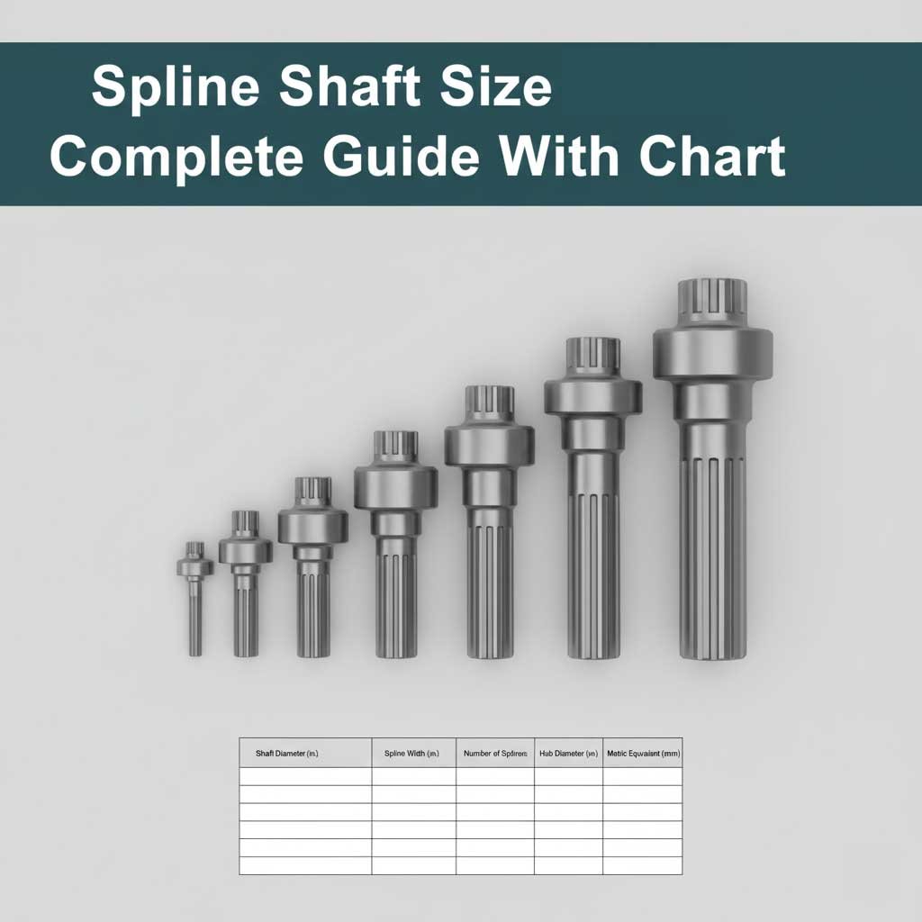
Spline Shaft Size Chart
Here is a simplified spline shaft size chart showing common dimensions. Note: Exact sizes vary by standard (ANSI, ISO, DIN), so always double-check before machining.
🔹 Metric Spline Shaft Size Chart (ISO / DIN Reference)
| Shaft Diameter (mm) | No. of Splines | Major Diameter (mm) | Minor Diameter (mm) | Pressure Angle |
|---|---|---|---|---|
| 10 | 6 | 10.0 | 8.4 | 30° |
| 15 | 6 | 15.0 | 13.2 | 30° |
| 20 | 8 | 20.0 | 17.6 | 30° |
| 25 | 8 | 25.0 | 22.6 | 30° |
| 30 | 10 | 30.0 | 27.0 | 30° |
| 40 | 10 | 40.0 | 36.0 | 30° |
| 50 | 12 | 50.0 | 45.0 | 30° |
| 60 | 12 | 60.0 | 54.0 | 30° |
| 80 | 16 | 80.0 | 72.0 | 30° |
| 100 | 16 | 100.0 | 90.0 | 30° |
🔹 Imperial Spline Shaft Size Chart (ANSI B92.1 Reference)
| Shaft Diameter (inches) | No. of Splines | Major Diameter (in) | Minor Diameter (in) | Pressure Angle |
|---|---|---|---|---|
| 1/2 | 6 | 0.500 | 0.430 | 30° |
| 3/4 | 6 | 0.750 | 0.670 | 30° |
| 1.0 | 8 | 1.000 | 0.900 | 30° |
| 1.25 | 10 | 1.250 | 1.125 | 30° |
| 1.5 | 10 | 1.500 | 1.375 | 30° |
| 2.0 | 12 | 2.000 | 1.830 | 30° |
| 2.5 | 12 | 2.500 | 2.300 | 30° |
| 3.0 | 16 | 3.000 | 2.760 | 30° |
| 3.5 | 16 | 3.500 | 3.200 | 30° |
| 4.0 | 20 | 4.000 | 3.650 | 30° |
Also Read:
Real-World Applications of Spline Shafts
Automotive Industry – Used in gearboxes, axles, and steering systems.
Aerospace – Jet engines rely on splines for power transmission in turbine stages.
Robotics – Precision splines help in robotic joints where accuracy is key.
Agriculture – Tractor PTO (Power Take-Off) shafts use splines to connect implements.
Industrial Equipment – Heavy machines like excavators use splines to connect hydraulic pumps and gearboxes.
Common Problems with Spline Shafts
Even with standardized sizes, mistakes happen. Common issues include:
Misalignment: Leads to uneven wear.
Improper Fit: Too loose → backlash; too tight → assembly issues.
Excessive Wear: Caused by poor lubrication.
Wrong Standard: Mixing DIN, ISO, or ANSI dimensions results in incompatibility.
Always ensure lubrication, correct alignment, and the right size selection using a trusted spline shaft chart.
Also Read:
Tips for Machinists and Engineers
Always identify the standard (ANSI, ISO, DIN) before cutting splines.
Use proper cutting tools — hobbing, broaching, or milling depending on type.
Double-check fit tolerances — loose fits for sliding, tight fits for fixed assemblies.
Maintain good lubrication in high-load splines to prevent wear.
Keep a laminated spline size chart near your machines for quick reference.
Also Read:
Conclusion
The spline shaft size chart is more than just a table of numbers — it’s a critical guide for ensuring torque is transmitted reliably across countless machines worldwide.
By selecting the correct spline size, engineers and machinists can guarantee:
Strong, balanced torque transfer
Long-lasting mechanical connections
Safer, smoother machinery performance
Whether you are designing a gearbox, repairing a tractor PTO shaft, or working on aerospace components, the spline shaft size chart is your trusted reference for precision and reliability.
A shaft with ridges may look simple, but in reality, it’s the hidden backbone of modern mechanical power transmission.
Also Read: