
Couplings are essential mechanical components used to connect two shafts together for efficient power transmission. Selecting the correct coupling size is critical to ensure smooth operation, safety, and long equipment life. An improperly sized coupling can lead to excessive vibration, misalignment, noise, premature wear of components, increased maintenance costs, and in severe cases, complete system failure or breakdown.
What Is a Coupling?
Why Coupling Size Matters
Understand Coupling Size Terminology
Understanding coupling size terminology is essential for making the right selection and ensuring reliable performance in mechanical systems. Familiarity with these key dimensions and ratings helps prevent installation issues, improves compatibility with shafts and equipment, and ensures the coupling can handle operational demands. Knowing what each term means allows engineers and technicians to choose couplings that deliver efficiency, durability, and safe operation.
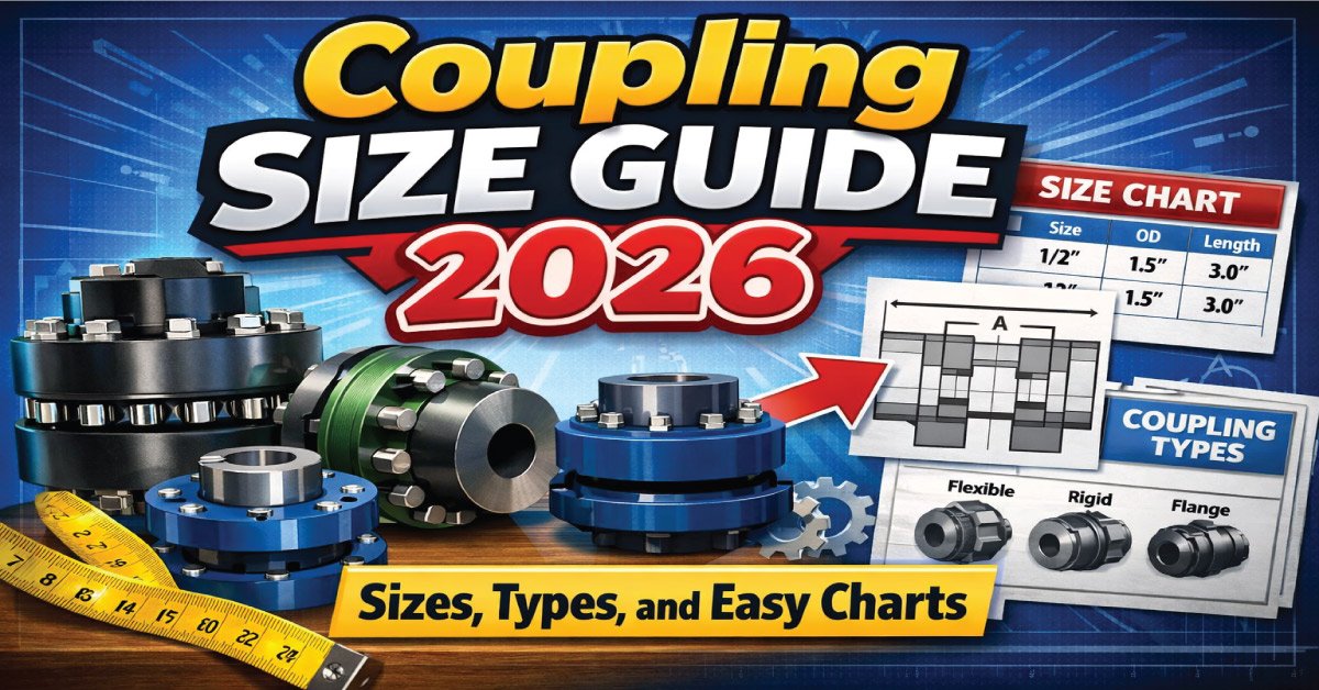
Bore Size – inner diameter of the coupling
Outside Diameter (OD) – total external width
Length – axial length of coupling
Torque Rating – maximum torque it can handle
Types of Couplings and Size Considerations
Selecting the right coupling type is just as important as choosing the correct size. Each coupling design serves different alignment, torque, and vibration requirements, which directly influence sizing criteria. Understanding how various coupling types differ in construction and performance helps ensure proper fit, reliable power transmission, and long-term equipment protection across a wide range of industrial applications.

1-Rigid Couplings
Rigid couplings connect shafts directly with no flexibility, providing precise alignment and strong torque transmission. They are ideal for applications with minimal misalignment and steady loads. Proper sizing is crucial to avoid shaft damage or excessive stress, as these couplings cannot compensate for angular or parallel misalignment.
2-Flexible Couplings
Flexible couplings can accommodate misalignment, vibration, and shock loads, making them suitable for a wide range of applications. Correct sizing ensures that torque is transmitted efficiently without overloading or premature wear. Misalignment tolerance and environmental conditions must be considered when selecting the right flexible coupling.
3-Jaw Couplings
Jaw couplings feature an elastomeric spider that absorbs shock and dampens vibration. Sizing considerations include bore range, torque capacity, and spider material. Proper selection prevents wear, maintains alignment, and ensures reliable torque transmission under varying operating conditions.
4-Gear Couplings
Gear couplings transmit high torque between shafts while allowing for slight misalignment. Accurate sizing is essential to handle load demands and minimize backlash. Consider shaft diameter, torque rating, and lubrication requirements when selecting gear couplings for heavy-duty applications.
5-Grid Couplings
Grid couplings use a metal grid to absorb shock loads and vibration. Correct sizing ensures durability, efficient torque transmission, and reduced maintenance. Factors such as torque rating, shaft alignment, and operating speed must be evaluated to prevent premature failure.
6- Oldham Couplings
Oldham couplings compensate for lateral and angular misalignment while transmitting torque. Proper sizing involves selecting the correct bore diameter, torque capacity, and hub type. This ensures smooth operation, reduced vibration, and extended service life.
Each type has its own sizing standards.
Also Read:
Factors Affecting Coupling Size Selection
Selecting the correct coupling size depends on several critical operating and design factors. Evaluating these elements helps ensure the coupling can handle load demands, accommodate movement, and perform reliably under actual working conditions. Considering these aspects early in the design process reduces the risk of failure, improves efficiency, and supports long-term, trouble-free equipment operation.
Shaft diameter
Torque requirements
Speed (RPM)
Misalignment tolerance
Environmental conditions
Shaft Diameter and Bore Size Relationship
Understanding the relationship between shaft diameter and bore size is essential for ensuring a secure, efficient, and vibration-free coupling installation. A correct match allows proper torque transmission and prevents damage to both the shaft and coupling. Even small mismatches can lead to slippage, misalignment, premature wear, and costly equipment failure over time.
Shaft Diameter vs Standard Bore Size
| Shaft Diameter (mm) | Bore Size (mm) | Typical Application |
|---|---|---|
| 10 | 10 | Small motors, fans |
| 20 | 20 | Pumps, conveyors |
| 30 | 30 | Mixers, compressors |
| 40 | 40 | Heavy machinery |
| 50 | 50 | Industrial drives |
Torque Requirements Explained
Torque refers to the rotational force that a coupling transmits between connected shafts. Selecting a coupling with a torque rating higher than the system’s actual requirement is essential to prevent overload, reduce wear, and ensure reliable operation. This ensures the coupling can handle peak loads, maintain performance, and extend the lifespan of both the coupling and the machinery.

Speed (RPM) and Its Impact on Coupling Size
Misalignment Tolerance and Coupling Size
Properly accounting for misalignment is crucial when selecting a coupling, as excessive misalignment can cause vibration, wear, and premature failure. Understanding the types of misalignment and how different couplings accommodate them ensures optimal performance, longer service life, and reduced maintenance. Flexible couplings offer more adaptability in real-world applications.
Angular
Parallel
Axial
Flexible couplings allow more tolerance and may require slightly different sizing than rigid ones.
Environmental Conditions to Consider
Environmental factors such as temperature, moisture, dust, and exposure to chemicals can significantly impact the performance and durability of a coupling. In harsh or corrosive conditions, it may be necessary to select larger couplings or those with specialized coatings and materials to resist wear, corrosion, and degradation, ensuring reliable operation and extended service life.
Standard Coupling Size Chart (Metric)
A standard coupling size chart provides a quick reference for selecting the right coupling based on bore range, torque capacity, and physical dimensions. Using standardized sizes ensures compatibility with shafts and equipment, simplifies maintenance, and helps prevent overloading. This metric chart guides engineers in matching couplings to application requirements efficiently and accurately.
Metric Coupling Size Chart
| Coupling Size | Bore Range (mm) | Max Torque (Nm) | OD (mm) | Length (mm) |
|---|---|---|---|---|
| 90 | 10–22 | 35 | 50 | 40 |
| 110 | 15–28 | 70 | 60 | 45 |
| 130 | 20–38 | 140 | 75 | 55 |
| 150 | 30–45 | 280 | 90 | 65 |
| 180 | 40–55 | 500 | 110 | 75 |
Standard Coupling Size Chart (Imperial)
Selecting the correct coupling in imperial units requires a clear understanding of bore range, torque capacity, and physical dimensions. Standardized charts simplify this process, ensuring proper fit, reliable power transmission, and reduced risk of equipment failure. Engineers can use this reference to quickly match couplings to shafts and operational requirements.
Imperial Coupling Size Chart
| Coupling Size | Bore Range (inches) | Max Torque (lb-in) | OD (inches) | Length (inches) |
|---|---|---|---|---|
| L035 | 0.25–0.50 | 40 | 1.4 | 1.1 |
| L050 | 0.38–0.75 | 100 | 2.0 | 1.4 |
| L075 | 0.50–1.00 | 200 | 2.6 | 1.9 |
| L090 | 0.75–1.25 | 360 | 3.3 | 2.2 |
| L110 | 1.00–1.50 | 600 | 4.1 | 2.6 |
Flexible vs Rigid Coupling Size Differences
Rigid couplings demand precise alignment and exact sizing because they transmit torque without accommodating misalignment, making correct measurements critical. Flexible couplings, on the other hand, can tolerate minor shaft misalignments and slight angular or parallel deviations. This flexibility often allows for slightly larger bore sizes, making installation easier and reducing stress on connected machinery.

Jaw Coupling Size Guide
Choosing the right jaw coupling size ensures efficient torque transmission, vibration damping, and long service life. By understanding bore range, torque capacity, and spider material, engineers can match couplings to shaft requirements and operating conditions. Proper selection minimizes downtime, protects equipment, and maintains smooth, reliable performance across various industrial applications.
Jaw Coupling Size Chart
| Jaw Coupling Size | Bore Range (mm) | Max Torque (Nm) | Spider Type |
|---|---|---|---|
| J-095 | 6–16 | 18 | Urethane |
| J-110 | 10–20 | 35 | NBR |
| J-130 | 14–30 | 70 | Hytrel |
| J-150 | 20–40 | 140 | Urethane |
| J-190 | 30–50 | 280 | Hytrel |
Also Read:
How to Measure for Correct Coupling Size
To select the right coupling size, first measure the shaft diameter using a precise caliper, checking multiple points for wear. Inspect the keyway width and depth for a proper fit. Measure the shaft separation to ensure correct alignment. Finally, determine the torque and speed requirements to choose a coupling that safely handles operational loads and ensures reliable performance.
1- Measure Shaft Diameter
Use a precise caliper to measure the diameter of each shaft. Accurate measurement ensures the coupling fits snugly, avoiding misalignment or slippage. Measure at multiple points to account for wear or irregularities. Record the largest diameter for selecting the coupling.
2- Check Shaft Keyway Size
Examine the keyway on the shafts carefully. Measure its width and depth to ensure the coupling’s key fits properly. A correct keyway match prevents rotational slippage and maintains torque transmission. Verify tolerances to avoid stress or damage to the shaft or coupling.
3- Measure Shaft Separation
Determine the center-to-center distance between the shafts. Proper separation ensures the coupling operates within its designed axial and radial limits. This measurement prevents excessive vibration, misalignment, and premature wear of the coupling components.
4- Determine Torque and Speed Requirements
Calculate the torque and operating speed for the application. Choose a coupling that can handle peak torque without slipping and sustain continuous operation at the required RPM. Matching these parameters ensures efficient power transmission and longer coupling life.
Also Read:
Step-by-Step Coupling Size Selection Process
Selecting the correct coupling size is critical for reliable power transmission and long equipment life. This process involves identifying the appropriate coupling type, measuring shaft diameters accurately, calculating torque loads, checking speed ratings, verifying misalignment tolerances, and choosing the correct bore and outer diameter. Following these steps ensures optimal fit, performance, and durability.
1- Identify Coupling Type
Begin by selecting the appropriate coupling type for your application. Consider factors such as torque requirements, misalignment tolerance, environmental conditions, and shaft configuration. Different types—rigid, flexible, gear, or elastomeric—serve distinct purposes. Choosing the correct type ensures smooth power transmission, minimizes wear, and prolongs the lifespan of both the coupling and connected equipment.
2- Measure Shaft Diameter
Accurately measure the diameter of each shaft using a precise caliper. Take measurements at multiple points to account for irregularities, wear, or ovality. Correct shaft sizing ensures the coupling fits snugly without slippage or excessive stress. Recording the largest diameter helps in selecting the appropriate coupling size, providing reliable torque transmission and optimal alignment.
3- Determine Torque Load
Calculate the torque load the coupling must transmit under normal and peak operating conditions. Consider both starting torque and dynamic loads to ensure the coupling can handle the stresses without failure. Proper torque assessment prevents slippage, reduces wear on shafts and coupling components, and ensures consistent, efficient power transfer during operation.
4- Check Speed Rating
Verify the coupling’s maximum allowable operating speed relative to your application. Exceeding speed limits can cause excessive vibration, heat buildup, and premature failure. Select a coupling rated for the required RPM and operating conditions. Matching speed ratings ensures safety, reliability, and long-term performance of the coupling and connected machinery.
5- Verify Misalignment Tolerance
Determine the allowable angular, parallel, and axial misalignment between shafts. The coupling must accommodate operational misalignment without overstressing components. Checking misalignment tolerance prevents vibration, wear, and potential damage. Choosing a coupling with adequate flexibility ensures smooth operation, reduces maintenance needs, and maintains efficient power transmission between connected shafts.
6- Choose Correct Bore and OD
Select a coupling with a bore that precisely matches the shaft diameter and an outer diameter that meets torque transmission requirements. Correct sizing ensures proper fit, prevents slippage, and distributes loads evenly. Proper bore and OD selection optimizes coupling performance, reduces stress on shafts, and guarantees long-lasting, efficient operation in alignment-sensitive applications.
Common Mistakes in Coupling Sizing
Selecting the wrong coupling size can lead to inefficiency, premature wear, and equipment failure. Common mistakes include ignoring torque requirements, failing to account for shaft misalignment, choosing an incorrect bore size, or overlooking environmental factors such as temperature, dust, or moisture. Avoiding these errors ensures smooth, reliable operation and longer equipment life.
Ignoring torque requirements
Not considering misalignment
Choosing wrong bore size
Overlooking environmental factors
Avoiding these mistakes ensures smooth operation.
Industry Standards for Coupling Sizes
Coupling sizes are typically designed according to established industry standards to ensure compatibility and reliability. Common standards include ISO (International Organization for Standardization), ANSI (American National Standards Institute), and DIN (Deutsches Institut für Normung). Following these standards simplifies replacement, maintenance, and sourcing of parts, while ensuring consistent performance across different equipment and manufacturers.

ISO (International Organization for Standardization)
ANSI (American National Standards Institute)
DIN (Deutsches Institut für Normung)
Using standard sizes simplifies replacement and maintenance.
Also Read:
Complete Tee Fitting Size Guide 2026 with PDF Chart
Coupling Size Guide for Pumps
Pump applications generally require flexible couplings that accommodate slight misalignment while transmitting torque efficiently. Coupling size should be selected based on motor power, rotational speed (RPM), and shaft diameter. Oversizing the coupling slightly is often safer than undersizing, as it reduces the risk of premature wear, vibration, and unexpected downtime, ensuring reliable pump operation.
Coupling Size Guide for Motors
Motor couplings must precisely match the shaft diameter and torque output to ensure efficient power transmission. High-speed motors demand couplings that are well-balanced to minimize vibration and stress on components. Correct sizing enhances motor performance, prevents misalignment issues, reduces maintenance needs, and prolongs both the motor and coupling lifespan, maintaining safe and reliable operation.
Coupling Size Guide for Conveyors
Conveyor systems frequently use gear, chain, or flexible couplings to handle varying loads. Coupling size selection depends on factors like load weight, belt speed, shaft diameter, and alignment tolerances. Properly sized couplings reduce wear, vibration, and energy loss, ensuring smooth operation, minimal maintenance, and long-term reliability, even under continuous or heavy-duty conveyor usage.
How to Read Manufacturer Coupling Size Charts
Manufacturer coupling size charts are vital for selecting the right coupling for any application. They list essential specifications, including bore range, torque capacity, maximum RPM, and overall dimensions. By carefully comparing your equipment’s requirements with these charts, you can ensure proper fit, reliable performance, and prevent premature wear or operational issues.
Bore range
Torque capacity
Max RPM
Dimensions
Always cross-check your application data with these charts.
Custom Coupling Sizes: When Are They Needed?
Custom coupling sizes become necessary when standard options cannot meet specific application requirements. This includes situations with non-standard shaft sizes, limited installation space, the need for special materials to resist corrosion or temperature, or applications involving extreme torque. Custom designs ensure proper fit, reliable performance, and long-term equipment protection.
Shaft sizes are non-standard
Space is limited
Special materials are needed
Extreme torque is involved
Maintenance Tips Related to Coupling Size
Even with the correct coupling size, regular maintenance is crucial to ensure reliable operation and prevent unexpected failures. Routine inspections help detect early signs of wear, misalignment, or damage, allowing timely intervention. Proper care extends equipment life, maintains performance, and ensures the coupling continues to handle torque and load efficiently.
Cracks
Loose bolts
Wear on elastomers
Misalignment
Signs You Chose the Wrong Coupling Size
Choosing the wrong coupling size can lead to serious operational issues, reduced equipment life, and increased maintenance costs. Identifying early warning signs helps prevent major failures and downtime. Recognizing symptoms such as vibration, overheating, or unusual noise allows engineers to take corrective action and ensure the coupling properly matches the shaft, load, and operating conditions.
Excessive vibration
Overheating
Noise
Frequent failures
Shaft damage
If you notice these, reassess your coupling size.
Benefits of Using the Correct Coupling Size
Choosing the correct coupling size is essential for optimal machinery performance. A properly sized coupling ensures efficient power transmission, minimizes wear, and reduces the risk of unexpected failures. This leads to decreased downtime, lower maintenance costs, longer equipment life, and enhanced safety for both operators and connected systems.

Increased efficiency
Reduced downtime
Longer equipment life
Lower maintenance costs
Improved safety
Coupling Size Guide for Heavy Machinery
Heavy machinery places significant demands on couplings due to high torque, heavy loads, and continuous operation. Selecting the correct coupling size ensures reliable power transmission, reduces wear, and prevents costly downtime. Always consider couplings with higher torque ratings and built-in safety factors to handle unexpected loads and maintain long-term performance under challenging industrial conditions.
Digital Tools for Coupling Size Selection
Final Thoughts
Selecting the correct coupling size goes beyond simply fitting components together—it ensures reliable, efficient, and safe operation of your machinery. By carefully evaluating factors such as shaft diameter, torque load, operating speed, misalignment tolerance, and environmental conditions, you can choose a coupling that optimizes performance, reduces maintenance, prevents downtime, and prolongs the lifespan of both the coupling and connected equipment.
FAQs:
What is the size of coupling?
Coupling size refers to the dimensional specification of a coupling that connects two shafts or pipes. It is usually defined by bore diameter, outside diameter, length, and torque capacity. The correct coupling size ensures proper alignment, power transmission, and safe mechanical operation.
How to determine coupling size?
To determine coupling size, measure the shaft or pipe diameter, identify the required torque and speed, and consider application factors such as misalignment and load. Matching these values with manufacturer size charts helps select the correct coupling for reliable performance.
How to measure a coupling size?
Coupling size is measured using calipers or measuring tools to check bore diameter, overall length, and outer diameter. Shaft size, keyway dimensions, and spacing between connected components should also be measured accurately to ensure the coupling fits and operates correctly.
What is coupler size?
Coupler size describes the internal and external dimensions of a coupler used to join shafts, pipes, or hoses. It typically includes inner diameter, length, and pressure or torque rating. Proper coupler size ensures a secure connection and prevents leakage or mechanical failure.
What is a 3-piece coupling?
A 3-piece coupling consists of two hubs and one flexible element positioned between them. This design allows easy installation and replacement without moving connected shafts, making it ideal for applications requiring vibration absorption, misalignment tolerance, and simplified maintenance.