
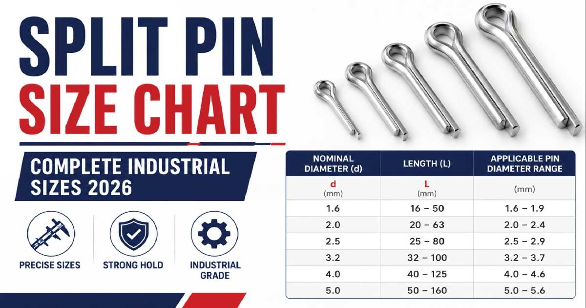
Split pins are small but extremely important mechanical fasteners used in engineering, automotive, and construction applications. Despite their simple design, they play a critical role in preventing nuts, bolts, and other fasteners from loosening due to vibration or movement.
Understanding the split pin size chart is essential for selecting the correct pin for safe and reliable assembly. A wrong size can lead to joint failure, loosening of parts, or even mechanical breakdown in critical systems.
This complete guide explains split pins, standard size charts, measurements, applications, types, and how to choose the correct size for your project.
What Is a Split Pin?
A split pin (also known as a cotter pin) is a simple but important mechanical fastener made from a single piece of metal wire bent into two prongs. After insertion into a drilled hole, these prongs are separated to lock components securely and prevent accidental loosening.
Uses of Split Pin
Split pins are widely used in mechanical assemblies where safety locking and vibration resistance are required. They act as a secondary locking device to ensure that fasteners do not loosen during operation, especially in moving or rotating systems.
It is commonly used to:
- Secure castellated nuts
- Lock bolts in place
- Prevent accidental loosening
- Act as a safety locking device
Once inserted into a hole, the two legs of the pin are bent outward to prevent it from slipping out.
Why Split Pin Size Matters
Split pin size is critical for ensuring mechanical safety, stability, and proper locking performance. The correct size ensures a tight fit, while incorrect sizing can lead to failure, loosening, or damage to connected components in mechanical systems.
Problems with Incorrect Split Pin Size
Using the wrong split pin size can reduce the reliability of the entire assembly. It may fail under vibration, cause improper locking, or even lead to mechanical breakdown in critical applications.
If the pin is too small:
- It may slip out easily
- It cannot hold the load properly
- It may fail under vibration
If the pin is too large:
- It may not fit into the hole
- It may damage the assembly
- It may cause improper locking
Correct sizing ensures:
- Secure fastening
- Vibration resistance
- Long-term reliability
- Safe mechanical operation
How Split Pin Sizes Are Measured
Split pins are sized based on key physical dimensions that determine fit, strength, and compatibility with the mating hole in mechanical assemblies.
1. Diameter (Wire Thickness)
The diameter refers to the thickness of the wire used to manufacture the split pin. It is the most important measurement because it determines whether the pin can fit properly into the drilled hole.
2. Length
Length is measured from the head of the split pin to its tip before bending. Proper length ensures enough material is available to bend the legs securely after installation.
3. Hole Size Compatibility
The split pin must match the hole size in the bolt, nut, or shaft. Correct compatibility ensures proper locking, prevents movement, and maintains safety in mechanical assemblies under load or vibration.
Standard Split Pin Size Chart (Metric)
The metric split pin size chart is commonly used in engineering, automotive, and industrial applications. It helps select the correct pin size based on diameter, length, and hole compatibility for safe and reliable mechanical fastening.
Metric Split Pin Size Overview
This chart lists standard metric split pin sizes used in various mechanical systems, from light electronics to heavy industrial equipment. Each size is matched with typical applications to ensure proper selection.
| Pin Diameter (mm) | Length (mm) | Recommended Hole Size (mm) | Typical Application |
|---|---|---|---|
| 1.0 mm | 10–20 mm | 1.0 mm | Small electronics, light assemblies |
| 1.2 mm | 12–25 mm | 1.2 mm | Precision instruments |
| 1.5 mm | 16–32 mm | 1.5 mm | Light mechanical fittings |
| 2.0 mm | 20–40 mm | 2.0 mm | Automotive components |
| 2.5 mm | 25–50 mm | 2.5 mm | General machinery |
| 3.0 mm | 30–60 mm | 3.0 mm | Heavy-duty mechanical use |
| 4.0 mm | 40–80 mm | 4.0 mm | Construction and industrial use |
| 5.0 mm | 50–100 mm | 5.0 mm | Heavy structural applications |
Standard Imperial Split Pin Size Chart
Imperial split pins are widely used in the USA and other regions that follow inch-based measurement systems. These sizes are suitable for automotive, mechanical, and structural applications.
Imperial Split Pin Size Overview
This chart includes standard imperial split pin sizes with diameter and length ranges, helping users choose the correct fastener for different load and assembly requirements.
| Pin Size | Diameter (inch) | Length Range | Typical Use |
|---|---|---|---|
| 1/32″ | 0.8 mm | 1/4″–1/2″ | Very small assemblies |
| 1/16″ | 1.6 mm | 1/2″–1″ | Light machinery |
| 3/32″ | 2.4 mm | 3/4″–1.5″ | Automotive fittings |
| 1/8″ | 3.2 mm | 1″–2″ | General engineering |
| 5/32″ | 4.0 mm | 1.5″–3″ | Heavy equipment |
| 3/16″ | 4.8 mm | 2″–4″ | Structural applications |
Types of Split Pins
Split pins are available in different types depending on load conditions, environment, and application requirements. Each type is designed to provide secure locking, vibration resistance, and long-term reliability in mechanical assemblies where safety and stability are important.
1. Standard Split Pin
The standard split pin is the most commonly used type in general mechanical applications. It is made from mild steel or stainless steel and is widely used for basic locking purposes where moderate strength and reliability are sufficient.
2. Heavy-Duty Split Pin
Heavy-duty split pins are designed with thicker wire construction to handle higher loads and mechanical stress. They are commonly used in industrial machinery where strong locking performance and resistance to vibration are required under demanding working conditions.
3. Stainless Steel Split Pin
Stainless steel split pins offer excellent corrosion resistance, making them ideal for outdoor, marine, and humid environments. They provide long-lasting performance and are preferred in applications where rust prevention and durability are critical factors.
4. Cotter Pins (Special Type)
Cotter pins are a special type of split pin with similar locking functionality but slightly different shapes or designs. They are used in high-stress mechanical systems where secure fastening and reliable safety locking are essential.
🔧 Explore Our Expert Guide 👉 Adjustable Wrench Size Chart: Complete Guide + PDF
Materials Used in Split Pins
Split pins are manufactured using different materials depending on strength requirements, environmental conditions, and application type. Each material offers unique advantages in terms of cost, durability, and corrosion resistance.
1. Mild Steel
Mild steel is the most commonly used material for split pins due to its low cost and general-purpose usability. It is suitable for basic mechanical applications where high corrosion resistance is not required.
2. Stainless Steel
Stainless steel split pins provide excellent resistance to rust and corrosion. They are widely used in marine, outdoor, and humid environments where long-term durability and reliability are essential.
3. Brass
Brass split pins are used in electrical and specialized applications. They are non-corrosive and non-sparking, making them suitable for environments where electrical safety and reduced spark risk are important.
How to Choose the Right Split Pin Size
Selecting the correct split pin size is essential for ensuring secure fastening, mechanical stability, and long-term performance. The right choice depends on hole size, load requirements, material type, and application conditions.
1. Check Hole Diameter
The split pin must fit properly into the hole without excessive force. A correct fit ensures secure locking while preventing damage to the pin or connected components during installation.
2. Select Proper Diameter
Pin diameter should match the load requirements of the application. Thicker pins are used for heavy loads, while thinner pins are suitable for light-duty mechanical assemblies.
3. Choose Correct Length
Proper length is important to ensure enough material is available for bending after insertion. This guarantees secure locking and prevents the pin from slipping out during operation.
4. Consider Material
Material selection depends on the operating environment. Stainless steel is preferred for outdoor use, while mild steel is suitable for general applications, and brass is used for electrical or non-sparking requirements.
5. Application Type
Different applications require different split pin strengths and sizes. Automotive systems typically use medium-sized pins, while industrial machinery requires heavy-duty pins for maximum safety and durability.
Step-by-Step Installation of Split Pins
Proper installation of split pins ensures secure locking and safe mechanical performance. Each step must be done carefully using proper tools to achieve correct bending, alignment, and stability, preventing loosening, vibration failure, or accidental disassembly during machine operation or mechanical load conditions.
Step 1: Insert the Pin
Insert the split pin through the hole in the bolt, shaft, or castellated nut. Ensure smooth entry without forcing it, as forcing may bend or damage the pin and reduce its strength, locking ability, and overall mechanical reliability.
Step 2: Align Properly
Before bending, ensure the split pin is fully inserted and correctly aligned inside the hole. Proper alignment allows both legs to bend evenly, improving locking strength, vibration resistance, and ensuring stable performance in mechanical assemblies under continuous load or movement.
Step 3: Bend the Legs
Use pliers to bend both legs of the split pin outward in opposite directions. This bending action locks the pin securely in place, preventing it from slipping out during vibration, rotation, or mechanical stress in working conditions.
Step 4: Secure Position
After bending, check that the split pin is tightly secured and cannot move. A properly secured pin provides strong locking performance, reduces risk of loosening, and ensures long-term reliability in machinery exposed to vibration or continuous mechanical operation.
Step 5: Final Check
Perform a final inspection to confirm the split pin is firmly installed and stable. This ensures safe operation, proper locking strength, and reduces the chance of mechanical failure before starting or resuming equipment or machinery use.
🔧 Explore Our Expert Guide 👉 Anchor Bolt Size Chart: Complete Guide + Pdf
Common Mistakes When Using Split Pins
Many users make simple but critical mistakes while installing split pins, which can reduce safety, strength, and performance. Avoiding these errors ensures better durability, proper locking, and reliable operation in mechanical systems and industrial applications under different working conditions.
1. Wrong Size Selection
Choosing the wrong split pin size can lead to loose fitting or overly tight installation. Both conditions reduce locking effectiveness, cause instability, and may result in mechanical failure, vibration loosening, or unsafe operation of connected components.
2. Not Bending Properly
Improper bending of split pin legs can cause the pin to loosen or fall out during operation. Correct bending is essential for secure locking, vibration resistance, and maintaining stability in moving mechanical systems under load conditions.
3. Reusing Old Pins
Reusing old split pins weakens their structural strength and reduces reliability. Worn pins may bend easily, fail under pressure, or break during operation, leading to unsafe conditions and reduced mechanical performance in critical applications requiring safety.
4. Incorrect Hole Size
Using a wrong hole size prevents proper installation of the split pin. A hole that is too small or too large results in poor fitting, weak locking strength, and increased risk of movement or mechanical failure during use.
5. Using Wrong Material
Selecting an incorrect material can lead to corrosion, rust, or breakage. Unsuitable materials reduce durability, especially in outdoor, marine, or high-moisture environments, affecting long-term performance and reliability of the mechanical assembly.
Applications of Split Pins
Split pins are widely used in many industries because they provide simple, reliable, and cost-effective locking solutions. They ensure safety and stability in mechanical systems where vibration resistance and secure fastening are essential for smooth operation.
🚗 Automotive Industry
Split pins are used in automotive systems to secure moving components and prevent loosening under vibration. They ensure safety and reliability in critical vehicle assemblies exposed to constant motion and mechanical stress.
Applications:
- Steering systems
- Suspension components
- Wheel assemblies
🏗️ Construction Industry
In construction, split pins are used to secure structural components and heavy machinery parts. They help maintain stability, strength, and safety in equipment used for building and infrastructure development projects.
Applications:
- Structural joints
- Heavy equipment fastening
⚙️ Machinery and Engineering
Split pins are essential in machinery for locking rotating parts and preventing unwanted movement. They ensure proper alignment and safe operation in industrial equipment used for continuous mechanical processes and heavy-duty applications.
Applications:
- Gear assemblies
- Rotating shafts
- Bearing locking
🚜 Agricultural Equipment
Agricultural machinery uses split pins to secure components exposed to rough field conditions. They provide durability, vibration resistance, and reliable performance in equipment used for farming and harvesting operations.
Applications:
- Tractor components
- Harvesting machines
🔧 Explore Our Expert Guide 👉 Lag Bolt Size Chart: Complete Guide + PDF
Advantages of Split Pins
Split pins offer several important advantages that make them widely used in mechanical and industrial applications. Their simple design, low cost, and reliable performance make them ideal for safety-critical and vibration-heavy environments.
- Simple and low-cost fastening system
- Easy to install and remove without special tools
- High resistance to vibration and movement
- Reliable locking for safety applications
- Suitable for a wide range of mechanical uses
Maintenance and Inspection
Regular maintenance and inspection of split pins is essential to ensure safe and reliable performance. Even though they are simple components, wear or damage can lead to failure, making periodic checks necessary in mechanical systems.
What to Check During Inspection
Inspect split pins regularly for signs of damage or wear. Early detection of issues helps prevent mechanical failure, ensures safety, and maintains the efficiency and reliability of the overall assembly during continuous operation.
- Rust or corrosion
- Loose bending
- Deformation
- Wear and tear
Damaged or worn split pins should always be replaced immediately to maintain safe and efficient mechanical operation.
Final Thoughts
The split pin size chart is an essential reference for engineers, mechanics, and technicians working with mechanical assemblies. These small fasteners play a major role in ensuring safety and preventing mechanical failures.
To summarize:
- Choose the correct diameter for strength
- Match length with assembly thickness
- Always bend properly after installation
- Use stainless steel for harsh environments
A properly selected split pin ensures secure, long-lasting, and vibration-resistant fastening in any mechanical system.