
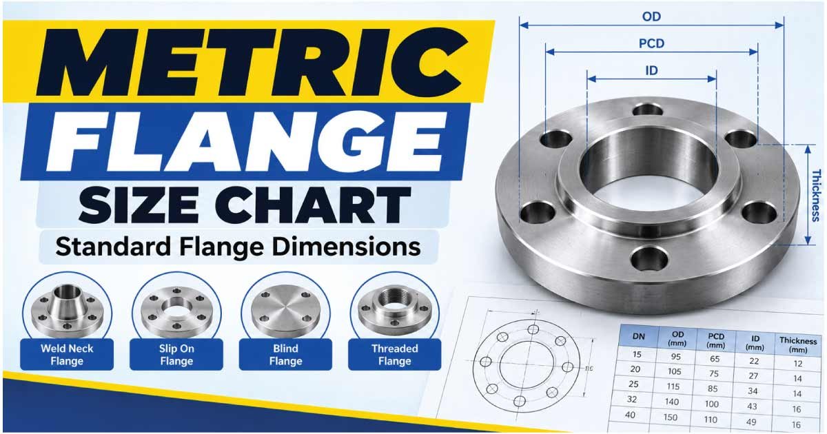
Choosing the correct flange requires more than matching the pipe diameter. A flange must also match the nominal pipe size, pressure class, bolt pattern, outside diameter, bore, thickness, facing, and applicable standard. That is why a metric flange size chart is useful when selecting or identifying components for industrial piping.
This guide explains common flange dimensions in millimeters, how metric and NPS sizes relate, and how to measure a flange accurately. It also covers common flange types, pressure ratings, bolt patterns, and the differences between major flange standards.
The dimensional chart below uses ASME B16.5 Class 150 as a practical reference. ASME B16.5 covers pipe flanges and flanged fittings from NPS 1/2 through NPS 24 for several pressure classes. Larger sizes fall under other standards such as ASME B16.47.
Because flange dimensions vary by standard, pressure class, facing, and flange type, always verify the applicable standard before ordering or fabricating a replacement.
Metric Flange Dimensions Explained
A flange is a mechanical component used to connect pipes, valves, pumps, fittings, and other equipment. Two flanges are normally joined with bolts and a gasket to create a serviceable connection.
When someone searches for metric flange dimensions, they may be looking for several different measurements.
Key Flange Measurements
The most important dimensions include:
- Flange outside diameter (OD): The total diameter across the flange.
- Bolt circle diameter (BCD): The diameter through the centers of the bolt holes.
- Bolt hole diameter: The diameter of each bolt hole.
- Number of bolt holes: The number of bolts used around the flange.
- Flange thickness: The thickness of the flange body.
- Bore diameter: The opening through which the pipe passes.
- Raised-face diameter: The diameter of the raised sealing surface on a raised-face flange.
- Hub diameter: Important on many weld-neck and other hubbed designs.
- Overall length: Particularly important for weld-neck and similar flanges.
These measurements work together. A flange with the correct outside diameter but the wrong bolt circle will not connect properly to its mating flange.
Nominal Size vs. Actual Dimension
One of the most important points to understand is that nominal pipe size is not necessarily the actual measured diameter.
For example, an ASME NPS 4 flange has a nominal pipe size of 4 inches, but its Class 150 flange outside diameter is approximately 229 mm (9.00 inches). Its bolt circle is approximately 191 mm (7.50 inches).
Therefore, do not identify a flange by measuring only its outside diameter.
ASME Class 150 Flange Size Chart in Metric Dimensions
The following chart provides commonly referenced ASME B16.5 Class 150 flange dimensions converted or presented in millimeters. It is intended as a dimensional reference, not a substitute for the applicable standard.
| NPS Size | Approx. DN | Flange OD (mm) | Bolt Circle (mm) | No. of Bolts | Bolt Size |
|---|---|---|---|---|---|
| 1/2 | DN 15 | 89 | 60.5 | 4 | 1/2 in |
| 3/4 | DN 20 | 98.5 | 69.9 | 4 | 1/2 in |
| 1 | DN 25 | 108 | 79.4 | 4 | 1/2 in |
| 1-1/4 | DN 32 | 117.5 | 88.9 | 4 | 1/2 in |
| 1-1/2 | DN 40 | 127 | 98.6 | 4 | 1/2 in |
| 2 | DN 50 | 152.4 | 120.7 | 4 | 5/8 in |
| 2-1/2 | DN 65 | 177.8 | 139.7 | 4 | 5/8 in |
| 3 | DN 80 | 190.5 | 152.4 | 4 | 5/8 in |
| 4 | DN 100 | 228.6 | 190.5 | 8 | 5/8 in |
| 5 | DN 125 | 254 | 215.9 | 8 | 3/4 in |
| 6 | DN 150 | 279.4 | 241.3 | 8 | 3/4 in |
| 8 | DN 200 | 342.9 | 298.5 | 8 | 3/4 in |
| 10 | DN 250 | 406.4 | 362.0 | 12 | 7/8 in |
| 12 | DN 300 | 482.6 | 431.8 | 12 | 7/8 in |
| 14 | DN 350 | 533.4 | 476.3 | 12 | 1 in |
| 16 | DN 400 | 596.9 | 539.8 | 16 | 1 in |
| 18 | DN 450 | 635 | 577.9 | 16 | 1-1/8 in |
| 20 | DN 500 | 698.5 | 635.0 | 20 | 1-1/8 in |
| 24 | DN 600 | 812.8 | 749.3 | 20 | 1-1/4 in |
The ASME Class 150 bolt pattern and flange outside diameters are standardized, while other dimensions can depend on the specific flange construction and design. Reference tables for Class 150 list the same general bolt-circle and bolt-count patterns shown above.
Important: The DN values in this table are nominal metric designations corresponding approximately to NPS sizes. They should not be interpreted as direct measurements of the flange bore or outside diameter.
Common Flange Types and Their Dimensions
A flange size chart becomes much more useful when the flange type is identified. Different flange designs can have different hub, bore, welding, and overall-length requirements even when they share the same nominal size and pressure class.
Weld Neck Flanges
A weld neck flange has a long tapered hub that is butt-welded to the pipe.
It is commonly selected where mechanical strength, controlled stress distribution, and reliable welded connections are important. The pipe bore and flange bore need to be compatible, particularly where internal flow characteristics matter.
Weld-neck dimensions include:
- Flange outside diameter
- Bolt circle
- Bolt-hole diameter
- Flange thickness
- Hub diameter
- Welding-neck dimensions
- Bore
- Overall length
Because the hub and neck geometry are part of the design, measuring only the flange OD is not enough to identify a weld-neck flange.
Slip-On Flanges
A slip-on flange fits over the outside of the pipe and is typically welded in place.
It is often used where installation and fabrication requirements make a simpler flange connection desirable. Its dimensions include the flange OD, bolt circle, bolt holes, thickness, bore, and internal welding area.
Socket Weld Flanges
Socket weld flanges have a recessed socket that receives the pipe.
They are commonly used for smaller pipe sizes. ASME B16.5 includes socket-welding flange dimensions for applicable sizes.
Threaded Flanges
A threaded flange contains internal threads rather than requiring a welded pipe connection.
They can be useful where welding is undesirable or impractical, but the pipe thread and flange thread must match correctly.
Lap Joint Flanges
A lap joint flange is used with a separate stub end. The flange can rotate around the stub end, which can simplify bolt-hole alignment.
This design is particularly useful where frequent dismantling or alignment is important.
Blind Flanges
A blind flange has no central pipe opening. It is used to close the end of a pipeline, nozzle, vessel connection, or other flanged opening.
Blind flanges are also useful when a system may need to be opened or extended later.
Metric Flange Size Standards
There is no single universal metric flange size chart that applies to every piping system. Several standards are used internationally.
ASME B16.5
ASME B16.5 is widely used for pipe flanges and flanged fittings. It uses NPS sizes and pressure classes, such as Class 150, 300, 600, 900, 1500, and 2500.
The nominal pipe size is expressed in inches, even when the physical dimensions are converted to millimeters.
EN 1092-1
European piping systems commonly use EN 1092-1, which uses DN nominal sizes and PN pressure designations such as PN 6, PN 10, PN 16, PN 25, and PN 40.
An EN flange should not automatically be considered interchangeable with an ASME flange simply because the DN and NPS sizes appear similar.
JIS Flange Standards
Japanese industrial piping may use JIS flange standards with their own dimensional and pressure classifications.
This means that a flange identified simply as “DN100” or “4-inch” is not sufficiently specified for procurement.
Why Standards Matter
Two flanges can have the same nominal pipe size but different:
- Outside diameters
- Bolt-circle diameters
- Bolt-hole sizes
- Number of bolts
- Thicknesses
- Facing dimensions
- Pressure ratings
Always identify the standard and pressure class before selecting a replacement.
Also Read:
Flange Pressure Classes and Ratings
Pressure class is another critical part of flange identification.
For ASME B16.5, common classes include:
- Class 150
- Class 300
- Class 400
- Class 600
- Class 900
- Class 1500
- Class 2500
The pressure class is not simply a universal pressure value that applies to every temperature and material. Allowable pressure depends on factors such as material, temperature, design conditions, and applicable code requirements.
A Class 300 flange is therefore not simply “twice as strong” as a Class 150 flange.
For example, the physical dimensions of Class 150 and Class 300 flanges differ. A Class 150 NPS 4 flange has an outside diameter around 229 mm, while a Class 300 NPS 4 flange is larger at approximately 254 mm.
Also Read:
How to Measure a Flange
If the original flange marking is missing or unreadable, careful measurement can help identify the flange.
Step 1: Measure the Outside Diameter
Use calipers or a suitable measuring tool to measure directly across the widest part of the flange.
Record the measurement in millimeters.
For example, a measurement close to 229 mm could correspond to an ASME Class 150 NPS 4 flange, but the remaining dimensions must also be checked.
Step 2: Measure the Bolt Circle
The bolt circle diameter is one of the most important identification measurements.
If you can measure from the center of one bolt hole to the center of the opposite bolt hole, that gives the approximate bolt circle diameter.
When opposite holes are not available, the measurement can be taken between appropriate hole centers and interpreted according to the bolt pattern.
Step 3: Count the Bolt Holes
Count every bolt hole around the flange.
Common patterns include:
- 4 holes
- 8 holes
- 12 holes
- 16 holes
- 20 holes
The number of holes helps distinguish flange sizes that may have similar outside diameters.
Step 4: Measure the Bolt Holes
Measure the diameter of the actual hole rather than assuming it from the bolt size.
Clearance holes are normally larger than the corresponding bolt diameter.
Step 5: Measure the Thickness
Place the measuring tool across the flange body and record its thickness.
Be careful not to include the raised face when comparing your measurement with a table that specifies flange thickness separately from facing dimensions.
Step 6: Measure the Bore
Measure the internal opening.
The bore is especially important for weld-neck, slip-on, socket-weld, and other flanges where the pipe connection interacts directly with the flange.
Step 7: Identify the Facing
Determine whether the flange has:
- Flat face
- Raised face
- Ring-type joint
- Other specified facing arrangement
Facing geometry can be essential for gasket compatibility and mating connections.
Also Read:
Metric Flange Dimensions: What Should You Match?
When replacing a flange, match more than the nominal pipe size.
Critical Dimensions
At minimum, verify:
- Nominal pipe size
- Applicable standard
- Pressure class or PN rating
- Flange type
- Outside diameter
- Bolt-circle diameter
- Number of bolt holes
- Bolt-hole diameter
- Bore
- Flange thickness
- Facing type
- Material specification
A replacement should be selected based on the complete specification rather than one matching measurement.
Metric vs. Inch Flange Sizes
One common source of confusion is the difference between metric measurements and metric nominal pipe sizes.
An ASME flange may have all of its dimensions measured in millimeters while still being identified using an NPS designation.
For example:
| NPS | Approx. DN | ASME Class 150 OD (mm) | ASME Class 150 Bolt Circle (mm) |
|---|---|---|---|
| 1 | DN 25 | 108 | 79.4 |
| 2 | DN 50 | 152.4 | 120.7 |
| 3 | DN 80 | 190.5 | 152.4 |
| 4 | DN 100 | 228.6 | 190.5 |
| 6 | DN 150 | 279.4 | 241.3 |
| 8 | DN 200 | 342.9 | 298.5 |
| 10 | DN 250 | 406.4 | 362.0 |
| 12 | DN 300 | 482.6 | 431.8 |
This demonstrates why DN 100 should not be treated as exactly 100 mm flange outside diameter.
DN is a nominal designation, not a direct statement of the flange’s external measurement.
Common Flange Selection Mistakes
Incorrect flange selection can lead to installation problems, leakage, alignment issues, or an unsuitable pressure connection.
Using Only Pipe Diameter
Matching the pipe diameter alone is insufficient.
A 4-inch pipe connection could involve different flange standards and pressure classes, each with different bolt patterns and dimensions.
Mixing Standards Without Verification
An ASME flange and an EN flange may have similar nominal sizes but different drilling patterns.
Always compare the complete dimensional specification before assuming interchangeability.
Ignoring the Pressure Class
A flange must be suitable for the system’s design pressure and temperature.
Do not substitute a flange simply because its bolt holes appear to line up.
Measuring the Outside Diameter Only
Several flange configurations can have similar external dimensions.
Check the bolt circle, bolt-hole count, bore, thickness, and facing as well.
Confusing Bolt Diameter With Bolt-Hole Diameter
A bolt passes through a clearance hole, so the hole is generally larger than the bolt itself.
When reading a flange chart, determine whether the listed dimension refers to the bolt, bolt hole, or bolt circle.
Tips for Using a Flange Size Chart
A flange dimension chart is most useful when combined with the actual component markings and project specifications.
Before purchasing a flange:
- Record the nominal pipe size.
- Identify the flange type.
- Check the standard.
- Confirm the pressure class or PN rating.
- Measure the flange OD.
- Measure the bolt circle.
- Count the bolt holes.
- Check bolt-hole diameter.
- Measure thickness and bore.
- Confirm the facing.
- Verify the material and service requirements.
- Compare the dimensions against the manufacturer’s drawing or applicable standard.
For critical piping systems, use the governing standard and approved engineering documentation rather than relying only on a general online chart.
Frequently Asked Questions About Metric Flange Sizes
What is a metric flange size?
A metric flange size normally refers to a flange used with a DN-based piping system or to flange dimensions expressed in millimeters. However, a flange can also have its dimensions given in millimeters while using an NPS designation, as with ASME B16.5.
Is DN the same as flange outside diameter?
No. DN is a nominal size designation, not the outside diameter of the flange. For example, DN 100 is commonly associated with NPS 4, but an ASME Class 150 NPS 4 flange has an outside diameter of approximately 229 mm.
What is the most important flange measurement?
There is no single measurement that identifies every flange. The most useful combination is the standard, pressure class, nominal size, flange type, outside diameter, bolt circle, bolt-hole pattern, bore, and thickness.
Are Class 150 and Class 300 flanges interchangeable?
Generally, they should not be treated as interchangeable simply because they have the same nominal pipe size. Their dimensions and pressure-rating requirements can differ substantially.
How do I identify an unknown flange?
Start by checking for stamped markings. Then measure the outside diameter, bolt circle, bolt-hole diameter, number of holes, thickness, and bore. Identify the facing and flange type, then compare the complete set of measurements with the relevant standard.
What does NPS mean on a flange?
NPS means Nominal Pipe Size. It is the nominal size system commonly used with ASME piping standards. NPS dimensions should not be interpreted as the actual measured inside or outside diameter of every component.
What does DN mean?
DN means nominal diameter and is widely used in metric and European piping systems. DN is a nominal designation rather than a guarantee that a pipe or flange measures exactly that many millimeters.
Conclusion
A reliable metric flange size chart should be used as a starting point for identification and selection, not as a substitute for the applicable piping standard. Flange dimensions depend on the nominal size, pressure class, standard, flange type, facing, and material.
For ASME systems, Class 150 provides a useful reference for common NPS flange dimensions, including outside diameter, bolt-circle diameter, bolt count, and bolt size. European and other international systems may use different dimensional standards and pressure designations.
When identifying an unknown flange, measure several characteristics rather than relying on one dimension. Confirm the OD, bolt circle, bolt-hole pattern, bore, thickness, facing, nominal size, and standard before purchasing or installing a replacement.
The safest approach for critical applications is to compare your measurements with the current applicable standard and the manufacturer’s dimensional drawing. This helps prevent mismatched bolt patterns, incorrect gasket selection, alignment problems, and unsuitable pressure connections.