
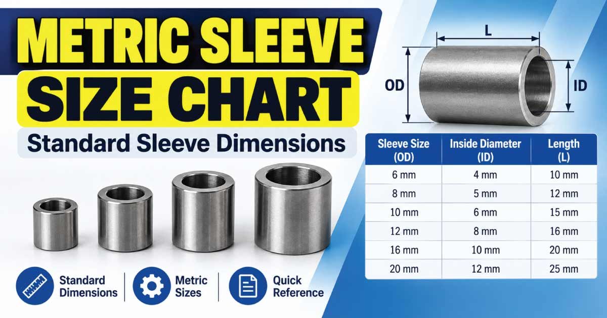
Choosing the right sleeve starts with more than knowing its nominal diameter. A sleeve may need to fit over a shaft, inside a housing, around a bearing, or between two mechanical components, so the bore diameter, outside diameter, length, wall thickness, and fit all matter.
This metric sleeve size chart explains the key dimensions used when selecting sleeves and bushings. It also covers common sleeve types, how to measure an existing sleeve, metric-to-inch considerations, material choices, tolerances, and practical selection tips.
Because sleeves are manufactured for many different applications, there is no single universal dimensional standard covering every sleeve. Exact dimensions can vary by manufacturer, sleeve type, material, tolerance class, and intended application. Always verify critical dimensions against the manufacturer’s drawing or applicable standard before ordering.
What Is a Metric Sleeve?
A metric sleeve is a cylindrical component designed to fit around, inside, or between other mechanical parts. It commonly provides spacing, alignment, support, wear resistance, or a controlled sliding or rotating interface.
The term sleeve can describe several products, including plain sleeves, spacer sleeves, bearing sleeves, shaft sleeves, repair sleeves, and cylindrical bushings. Their dimensions are normally expressed in millimeters.
The most important sleeve dimensions are:
- Inside diameter (ID): The diameter of the internal opening.
- Outside diameter (OD): The diameter across the outside surface.
- Length: The axial dimension from one end to the other.
- Wall thickness: The thickness of the sleeve wall.
- Chamfer: A beveled edge that may help installation.
- Bore tolerance: The permitted variation in the internal diameter.
- OD tolerance: The permitted variation in the outside diameter.
For a simple cylindrical sleeve, wall thickness can be calculated as:
Wall thickness = (Outside diameter − Inside diameter) ÷ 2
For example, a sleeve with a 30 mm outside diameter and a 20 mm inside diameter has a nominal wall thickness of 5 mm.
Metric Sleeve Size Chart
The following table provides common nominal dimensional combinations used as practical reference points, not a universal standard. Actual commercially available sleeves may use different dimensions or tolerances.
| Nominal ID (mm) | Nominal OD (mm) | Nominal Wall (mm) | Typical Length Range (mm) | General Use |
|---|---|---|---|---|
| 5 | 8 | 1.5 | 5–20 | Small mechanisms |
| 6 | 10 | 2.0 | 6–25 | Pins and shafts |
| 8 | 12 | 2.0 | 8–30 | Light machinery |
| 10 | 15 | 2.5 | 10–40 | General mechanical work |
| 12 | 16 | 2.0 | 12–50 | Shafts and spacers |
| 15 | 20 | 2.5 | 15–50 | Machinery assemblies |
| 16 | 22 | 3.0 | 16–60 | Bearings and shafts |
| 20 | 25 | 2.5 | 20–60 | General-purpose applications |
| 25 | 30 | 2.5 | 25–75 | Shaft support |
| 30 | 40 | 5.0 | 30–100 | Heavy mechanical assemblies |
| 40 | 50 | 5.0 | 40–100 | Industrial machinery |
| 50 | 60 | 5.0 | 50–125 | Larger shafts |
| 60 | 75 | 7.5 | 60–150 | Heavy-duty equipment |
These values should be treated as a sizing reference rather than a manufacturing specification. A sleeve with the correct nominal dimensions can still be unsuitable if its tolerance, material, surface finish, or fit is wrong.
Key Sleeve Dimensions Explained
Inside Diameter (ID)
The inside diameter is often the first measurement considered because it determines how the sleeve interacts with the shaft, pin, bolt, or other internal component.
For a sleeve installed over a shaft, the required ID depends on the intended fit. A freely rotating sleeve may require different clearance from a sleeve designed for a press or interference fit.
When measuring an existing sleeve, measure the bore at multiple points rather than relying on one reading. Wear, distortion, corrosion, or manufacturing variation can cause the bore to differ slightly from one location to another.
Outside Diameter (OD)
The outside diameter determines how the sleeve fits into a housing, bore, bracket, or surrounding component.
For a housing-mounted sleeve, OD can be particularly important because an incorrect diameter can result in excessive movement or make installation impossible.
Length
Sleeve length determines how much of the shaft or assembly the component supports or spaces.
A spacer sleeve, for example, may need a very specific length to establish the correct distance between bearings or other components. A shaft sleeve used as a wear surface may require enough length to cover the damaged or working section of a shaft.
Wall Thickness
Wall thickness affects the physical dimensions and available material between the ID and OD.
The basic relationship is:
OD = ID + 2 × wall thickness
This relationship is useful when a sleeve is described by its bore and wall thickness rather than by its outside diameter.
Metric Sleeve Types and Their Dimensions
Not every sleeve should be selected using the same criteria. The function of the sleeve determines which dimensions and specifications deserve the most attention.
Plain Sleeves and Bushings
Plain sleeves are cylindrical components commonly used to provide a sliding surface between two parts.
They may be manufactured from materials such as bronze, steel, stainless steel, polymer, or composite materials. Their dimensions can include:
- Bore diameter
- Outside diameter
- Overall length
- Wall thickness
- Chamfer dimensions
- Bore and OD tolerances
- Surface finish
A plain bushing must be selected according to both its dimensional requirements and its operating conditions.
Spacer Sleeves
Spacer sleeves maintain a defined distance between components.
Unlike a bearing sleeve, the primary purpose is often spacing and positioning rather than providing a sliding bearing surface.
Length is therefore especially important. Even a sleeve with the correct ID and OD may be unsuitable if its length does not produce the required assembly spacing.
Shaft Sleeves
A shaft sleeve fits over a shaft to protect or restore a working surface.
These sleeves may be used where a shaft surface is exposed to wear, corrosion, or repeated contact with a seal or other component. The sleeve must match the shaft diameter and the requirements of the surrounding component.
Flanged Sleeves
A flanged sleeve includes an enlarged section or flange at one end.
The additional flange diameter and thickness become important dimensions alongside the basic ID, OD, and sleeve length.
Flanged designs can help establish axial positioning or provide a shoulder against which another component can rest.
Bearing Sleeves
Some sleeves function as bearing surfaces, while others form part of bearing-related assemblies.
For these applications, dimensional accuracy becomes especially important because the sleeve may need to work with a rotating shaft, housing, lubricant, and specified clearance.
How to Measure a Metric Sleeve
Accurate measurement is essential when replacing an unknown sleeve.
1. Measure the Inside Diameter
Use an appropriate precision measuring instrument, such as an inside micrometer, bore gauge, or suitable caliper for less demanding measurements.
Take readings at different angular positions and, where practical, at different points along the bore.
Look for:
- Bore wear
- Taper
- Out-of-round conditions
- Damage
- Corrosion
- Contamination
Do not automatically assume the measured bore represents the original nominal size if the sleeve has been in service.
2. Measure the Outside Diameter
Measure the OD at several locations around the sleeve.
If the component is worn, distorted, or damaged, record the variation rather than using only the smallest or largest measurement.
3. Measure the Length
Measure from one end face to the other using a suitable precision instrument.
If the sleeve has a flange, shoulder, groove, or other feature, measure the relevant sections separately.
4. Calculate Wall Thickness
If the sleeve is a simple cylindrical design:
Wall thickness = (OD − ID) ÷ 2
For example:
- ID = 25 mm
- OD = 35 mm
- Difference = 10 mm
- Wall thickness = 5 mm
This calculation provides the nominal radial wall thickness.
5. Record Special Features
A replacement sleeve may also require measurements for:
- Flange diameter
- Flange thickness
- Grooves
- Oil holes
- Retaining features
- Chamfers
- Shoulders
- Keyways
- Slots
- Surface coatings
A sleeve with the correct basic diameter but the wrong special features may not work in the assembly.
Metric Sleeve Tolerances and Fits
Nominal dimensions alone do not completely describe a sleeve.
A sleeve specified as 20 mm does not necessarily have an exact 20.000 mm dimension. Manufacturing tolerances define the acceptable variation.
The required tolerance depends on the application and mating components.
Clearance Fit
A clearance fit provides intentional space between mating surfaces.
It may be appropriate when:
- One component must rotate freely.
- Thermal expansion needs to be accommodated.
- Lubrication requires clearance.
- Easy assembly and removal are important.
Transition Fit
A transition fit falls between a clear clearance fit and a strong interference fit.
Depending on actual dimensions and tolerances, the assembly may have slight clearance or slight interference.
Interference Fit
An interference fit means the mating dimensions are selected so the components assemble tightly.
This type of fit may be used when the sleeve must remain securely positioned in a housing or on a shaft.
The exact fit should be selected from the applicable engineering requirements rather than guessed from nominal sleeve dimensions.
Also Read:
Metric Sleeve Materials
Dimension selection is only one part of sleeve selection. The material must also suit the application.
Steel Sleeves
Steel sleeves offer strength and are widely used in mechanical applications.
Depending on the grade and treatment, steel can provide useful wear resistance and dimensional stability. Corrosion protection may be necessary in exposed environments.
Stainless Steel Sleeves
Stainless steel can be useful where corrosion resistance is an important consideration.
The appropriate stainless grade depends on the environment, temperature, chemical exposure, strength requirements, and other service conditions.
Bronze Sleeves
Bronze is commonly associated with plain bearing and bushing applications because of its useful friction and wear characteristics.
Different bronze alloys have different properties, so the material grade should be checked rather than treating all bronze sleeves as equivalent.
Polymer and Composite Sleeves
Polymer and composite materials can provide advantages such as low weight, corrosion resistance, or reduced lubrication requirements in certain applications.
Their suitability depends on load, temperature, speed, chemical exposure, and manufacturer specifications.
How to Choose the Correct Metric Sleeve Size
Selecting a sleeve should be treated as a complete dimensional and application-matching process.
Check the Mating Shaft
Start with the shaft, pin, or internal component.
Determine:
- Actual diameter
- Required fit
- Shaft condition
- Rotation or sliding requirements
- Operating temperature
A sleeve selected from nominal dimensions alone may fail to provide the required working clearance.
Check the Housing
If the sleeve installs into a housing, measure the housing bore and determine the required fit.
The sleeve’s OD must work with the housing dimensions and specified tolerance.
Confirm Sleeve Length
Length should match the assembly requirements.
For a spacer, length may directly control the position of bearings or other components. For a bushing, insufficient length may reduce the available support area.
Consider Operating Conditions
Think beyond dimensions. Consider:
- Radial load
- Axial load
- Rotation speed
- Sliding speed
- Temperature
- Lubrication
- Moisture
- Dust
- Chemicals
- Corrosive environments
- Expected service life
These conditions can influence both material and design selection.
Verify the Manufacturer’s Drawing
For critical machinery, use the manufacturer’s technical drawing or engineering specification.
The drawing may provide tolerances, surface finish, material grade, hardness, chamfers, and other details that cannot be determined from a basic sleeve size chart.
Also Read:
Metric Sleeve Sizes vs. Inch Sleeve Sizes
Metric sleeves are generally specified using millimeters, while inch-based products use inches or fractional inch dimensions.
The two systems can be converted, but conversion does not automatically make two sleeves interchangeable.
The basic relationships are:
1 inch = 25.4 mm
1 mm = 0.03937 inch
For example, a 25.4 mm dimension is exactly 1 inch. However, a nominal 25 mm sleeve is not the same size as a nominal 1-inch sleeve.
| Metric Dimension (mm) | Approx. Inches | Common Inch Reference |
|---|---|---|
| 6 mm | 0.2362 in | — |
| 8 mm | 0.3150 in | — |
| 10 mm | 0.3937 in | — |
| 12 mm | 0.4724 in | — |
| 15 mm | 0.5906 in | — |
| 20 mm | 0.7874 in | — |
| 25 mm | 0.9843 in | — |
| 25.4 mm | 1.0000 in | 1 in |
| 30 mm | 1.1811 in | — |
| 40 mm | 1.5748 in | — |
| 50 mm | 1.9685 in | — |
When replacing an inch sleeve with a metric component, check the actual mating dimensions and tolerances instead of choosing the closest numerical conversion.
Also Read:
Common Sleeve Selection Mistakes
Several errors can lead to poor fit or premature failure.
Choosing by Inside Diameter Alone
Two sleeves can have the same ID but completely different OD, length, wall thickness, and material.
Always check the complete dimensional specification.
Ignoring Tolerances
A nominally correct dimension may still produce the wrong fit if the tolerance is unsuitable.
For precision applications, confirm the complete tolerance specification.
Using a Worn Sleeve as the Only Reference
A used sleeve may have changed dimensions through wear or deformation.
Whenever possible, measure the mating shaft and housing as well as the old sleeve.
Assuming Similar Sleeves Are Interchangeable
Sleeves that look identical can have different materials, clearances, coatings, or manufacturing tolerances.
Compare the technical specifications before substitution.
Ignoring Temperature
Thermal expansion can affect clearances and fits, particularly where dissimilar materials are used.
Applications involving substantial temperature changes should be evaluated using the relevant material properties and engineering requirements.
Metric Sleeve Size Selection Checklist
Before ordering a replacement sleeve, verify the following:
- Inside diameter: Does it match the shaft or internal component?
- Outside diameter: Does it fit the housing or surrounding bore?
- Length: Is the axial dimension correct?
- Wall thickness: Is there enough material for the intended application?
- Fit: Is clearance, transition, or interference required?
- Material: Is it suitable for the load and environment?
- Surface finish: Is the mating surface appropriate?
- Temperature: Can the sleeve operate at the required temperature?
- Lubrication: Does the design require grease, oil, or dry operation?
- Special features: Are flanges, grooves, holes, or shoulders required?
- Tolerance: Does the manufacturer’s specification meet the application?
- Standard: Is the sleeve made to the relevant industry or manufacturer specification?
For a critical repair, verify these points against the equipment drawing or original part number whenever available.
Frequently Asked Questions
What are the standard dimensions of a metric sleeve?
There is no single standard dimension that applies to every metric sleeve. Common specifications include inside diameter, outside diameter, length, wall thickness, and tolerances. The available sizes depend on the sleeve type, manufacturer, material, and application.
How is sleeve size measured?
A sleeve is normally measured by its inside diameter, outside diameter, and length. For a plain cylindrical sleeve, wall thickness can then be calculated from the difference between OD and ID.
What is the difference between a sleeve and a bushing?
The terms are sometimes used interchangeably, but they can describe different products depending on the industry. A bushing commonly functions as a bearing or sliding element, while a sleeve may also be used for spacing, protection, alignment, or repair.
How do I know what sleeve diameter I need?
Measure the relevant mating components and determine the required fit. If the sleeve goes over a shaft, check the shaft diameter and required clearance or interference. If it fits into a housing, check the housing bore and required OD fit.
Can I replace an inch sleeve with a metric sleeve?
Sometimes, but not simply by choosing the nearest converted size. Even small dimensional differences can affect fit and function. Check the actual shaft, housing, tolerances, material, and application requirements before substitution.
Does sleeve wall thickness matter?
Yes. Wall thickness affects the sleeve’s overall dimensions and can influence its mechanical behavior, available wear material, and suitability for the application. It should be considered together with load, material, and design requirements.
Should I use a caliper to measure a sleeve?
A caliper can be useful for general measurements, especially on larger, less demanding components. For precision fits, however, more appropriate measuring equipment such as micrometers or bore gauges may be required.
Are metric sleeve sizes universal?
No. A metric dimension identifies the measurement system, but it does not guarantee a universal sleeve design. Different manufacturers and standards may specify different dimensions, tolerances, materials, and configurations.
Conclusion
A metric sleeve size chart is a useful starting point for identifying the dimensions of cylindrical sleeves, but selecting the correct component requires more than matching one number. Inside diameter, outside diameter, length, wall thickness, fit, tolerance, material, and operating conditions all influence whether a sleeve is suitable.
For general applications, use the dimensional chart to narrow down the required size. For precision machinery or safety-critical assemblies, verify the exact specification using the manufacturer’s drawing, original part information, or applicable engineering standard.
The most reliable approach is to measure the sleeve and its mating components, identify the required fit, and then confirm the complete specification before purchasing or machining a replacement.