
Whether you are a seasoned CNC machinist or just setting up your first milling operation, choosing the right end mill size can mean the difference between a perfect finish and a broken tool. This complete guide covers everything you need to know about CNC end mill sizes from reading a size chart to selecting the ideal diameter, flute count, and cutting length for your specific application.
What Is a CNC End Mill?
A CNC end mill is a type of milling cutter used in industrial milling applications. Unlike a drill bit, which cuts only at its tip, an end mill is capable of cutting in all directions — axially and radially. End mills are used for profiling, slotting, contouring, counter-boring, and plunging operations on CNC machining centers.
The size of an end mill directly affects cutting performance, surface finish, tool life, and material removal rate. That is why understanding the CNC end mill size chart is absolutely essential for every machinist.
Key Dimensions on a CNC End Mill Size Chart
Before reading a CNC end mill size chart, it is essential to understand the main dimensions that define tool performance. Each measurement directly affects cutting accuracy, surface finish, tool strength, and machining efficiency in milling operations.
Before diving into the full size chart, it is important to understand the key dimensions you will encounter:
1. Cutting Diameter (D)
Cutting diameter is the width of the actual cutting portion of the end mill that removes material during machining. It is one of the most important specifications because it directly determines the size of the cut and final machining accuracy.
- This is the diameter of the cutting portion of the end mill.
- This is the most critical measurement and determines the width of your cut.
A larger cutting diameter allows faster material removal, while a smaller diameter is used for fine detailing and precision work.
2. Shank Diameter
The shank diameter refers to the smooth cylindrical part of the tool that is held by the tool holder or collet in the CNC machine. It provides stability and ensures the tool is securely clamped during operation.
- This is the cylindrical portion that fits into the tool holder.
- It may or may not match the cutting diameter.
A strong and properly matched shank diameter helps reduce vibration and improves machining accuracy.
3. Flute Length (Length of Cut / LOC)
Flute length represents the length of the cutting edges on the end mill. It determines how deep the tool can cut into the material in a single pass without losing stability or efficiency.
- This is the length of the cutting edges on the end mill.
- This determines the maximum depth of a single pass.
Longer flute lengths allow deeper cuts, but shorter flutes generally provide better rigidity and surface finish.
4. Overall Length (OAL)
Overall length is the total length of the end mill from tip to the end of the shank. It helps determine tool reach and accessibility in deeper or complex machining operations.
- This is the total length of the end mill from tip to end of shank.
A longer overall length is useful for deep or hard-to-reach areas, but it may reduce tool rigidity compared to shorter tools.
5. Number of Flutes
The number of flutes refers to how many cutting edges are present on the end mill. This affects chip removal, cutting speed, and surface finish quality during machining.
- Common options are 2, 3, 4, and 6 flutes.
Fewer flutes allow better chip evacuation, while more flutes provide smoother surface finish and higher feed rates in certain materials.
6. Helix Angle
Helix angle is the angle of the cutting flutes around the tool body. It influences cutting action, chip removal, tool strength, and vibration control during machining.
- Typically 30°, 35°, 38°, or 45°.
A higher helix angle usually provides smoother cutting and better finish, while lower angles improve tool strength and stability in harder materials.
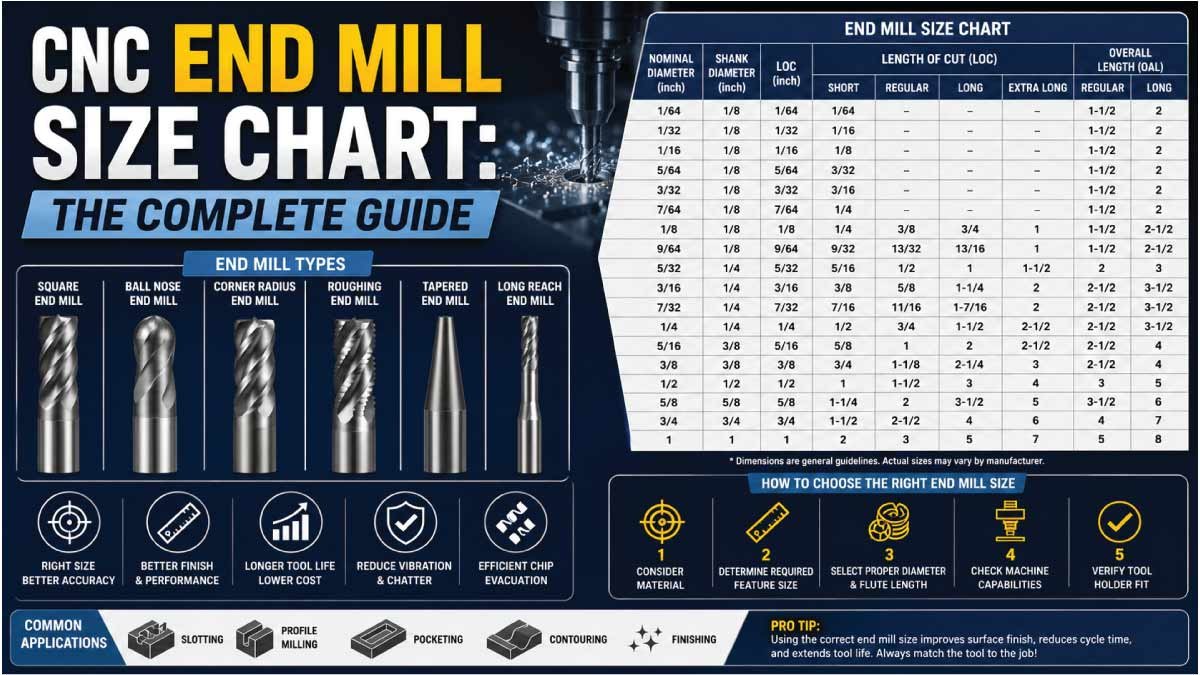
CNC End Mill Size Chart (Metric & Imperial)
A CNC end mill size chart helps machinists quickly choose the correct tool based on cutting diameter, shank size, flute length, and overall length. Below are standard reference sizes used in most CNC milling operations.
| Cutting Diameter | Shank Diameter | Flute Length (LOC) | Overall Length (OAL) | Common Flutes |
|---|---|---|---|---|
| 1 mm | 4 mm | 3 mm | 38 mm | 2 |
| 2 mm | 4 mm | 5 mm | 38 mm | 2 |
| 3 mm | 4 mm | 8 mm | 38 mm | 2–4 |
| 4 mm | 4 mm | 11 mm | 38 mm | 2–4 |
| 5 mm | 5 mm | 13 mm | 50 mm | 2–4 |
| 6 mm | 6 mm | 16 mm | 50 mm | 2–4 |
| 8 mm | 8 mm | 22 mm | 63 mm | 2–4 |
| 10 mm | 10 mm | 26 mm | 75 mm | 2–4 |
| 12 mm | 12 mm | 32 mm | 83 mm | 4 |
| 16 mm | 16 mm | 42 mm | 100 mm | 4 |
| 20 mm | 20 mm | 52 mm | 104 mm | 4–6 |
| 25 mm | 25 mm | 63 mm | 121 mm | 4–6 |
Standard Imperial (Inch) End Mill Sizes
| Cutting Diameter | Shank Diameter | Flute Length (LOC) | Overall Length (OAL) | Common Flutes |
|---|---|---|---|---|
| 1/16″ | 1/8″ | 1/8″ | 1-1/2″ | 2 |
| 1/8″ | 1/8″ | 1/4″ | 1-1/2″ | 2–4 |
| 3/16″ | 3/16″ | 3/8″ | 2″ | 2–4 |
| 1/4″ | 1/4″ | 5/8″ | 2-1/2″ | 2–4 |
| 5/16″ | 5/16″ | 13/16″ | 2-1/2″ | 2–4 |
| 3/8″ | 3/8″ | 1″ | 3″ | 2–4 |
| 1/2″ | 1/2″ | 1-1/4″ | 3″ | 2–4 |
| 5/8″ | 5/8″ | 1-5/8″ | 3-1/2″ | 4 |
| 3/4″ | 3/4″ | 2″ | 4″ | 4 |
| 1″ | 1″ | 2-1/2″ | 4-1/2″ | 4–6 |
End Mill Flute Count Guide
| Flutes | Best Use Case | Chip Clearance | Surface Finish |
|---|---|---|---|
| 2 | Aluminum, plastics, wood | Excellent | Good |
| 3 | General purpose, aluminum | Good | Good |
| 4 | Steel, stainless, alloys | Moderate | Excellent |
| 5–6 | Finishing passes, hardened materials | Limited | Superior |
End Mill Size Selection Quick Reference
| Application | Recommended Diameter | Flutes | Notes |
|---|---|---|---|
| Engraving / Fine detail | 0.5–2 mm / 1/64″–1/8″ | 2 | Use high RPM |
| PCB routing | 0.8–3.175 mm | 2 | Carbide required |
| General aluminum milling | 6–12 mm / 1/4″–1/2″ | 2–3 | High speed, flood coolant |
| General steel milling | 6–16 mm / 1/4″–5/8″ | 4 | Rigid setup required |
| Large pocket roughing | 12–25 mm / 1/2″–1″ | 4–6 | Use roughing end mill |
| 3D surface finishing | 3–10 mm ball nose | 2–4 | Small stepovers |
Tips for Extending End Mill Life
End mills are expensive cutting tools, and their performance directly affects machining cost, surface finish, and production efficiency. With proper usage and maintenance, you can significantly increase tool life and reduce breakage or premature wear.
1. Use the Correct Cutting Parameters
One of the biggest reasons end mills fail early is incorrect speed and feed settings. Running tools too fast generates excess heat, while too slow can cause rubbing instead of cutting.
- Always match RPM and feed rate to material type
- Avoid overloading the tool with excessive chip load
- Follow manufacturer cutting recommendations whenever possible
Proper cutting parameters reduce tool wear and improve machining consistency.
2. Avoid Excessive Tool Overhang
Tool rigidity plays a major role in tool life. The more the tool sticks out from the holder, the more vibration and deflection it experiences during cutting.
- Keep tool overhang as short as possible
- Use stub-length tools for deep cuts when feasible
- Ensure firm clamping in the tool holder
Less vibration = longer tool life and better surface finish.
3. Ensure Proper Chip Evacuation
Poor chip removal is one of the main causes of tool overheating and breakage. Chips trapped in the cutting zone increase friction and damage cutting edges.
- Use air blast, coolant, or vacuum systems
- Avoid recutting chips in pockets or deep cuts
- Use appropriate flute count for the material
Good chip evacuation keeps the cutting zone cool and stable.
Our Trending Post:
4. Use the Right Tool for the Material
Using the wrong end mill type for a material leads to rapid wear and poor performance. Each material requires a specific tool geometry and coating.
- Aluminum → polished 2-flute end mills
- Steel → 4-flute carbide end mills
- Hardened materials → coated high-performance tools
- Plastics → sharp, high-helix tools to reduce melting
Correct tool selection greatly extends tool life.
5. Maintain Proper Workholding
Loose or unstable workholding causes vibration, chatter, and uneven cutting forces that quickly damage end mills.
- Secure workpieces firmly using proper clamps or fixtures
- Avoid movement during machining operations
- Ensure flat and stable setup before cutting
Stable setups reduce tool stress and improve accuracy.
6. Use Coolant or Lubrication When Needed
Cooling plays a key role in reducing heat buildup, especially in metals like steel and stainless steel.
- Use flood coolant for steel and stainless steel
- Use mist or air for aluminum when appropriate
- Avoid overheating during long cutting cycles
Proper cooling protects cutting edges and extends tool life.
7. Avoid Full-Width Cuts When Possible
Full engagement cuts put extreme load on the tool and can lead to breakage or rapid wear.
- Use step-down or step-over strategies
- Take multiple shallow passes instead of one deep cut
- Optimize tool paths in CAM software
This reduces stress and improves machining efficiency.
8. Inspect and Replace Tools Regularly
Even high-quality end mills wear out over time. Using dull tools leads to poor surface finish and higher cutting forces.
- Check for chipped or worn cutting edges
- Replace tools before performance drops significantly
- Keep spare tools ready for production work
A sharp tool always performs better than a worn one.
Conclusion
Understanding the CNC end mill size chart is one of the most valuable skills a machinist can develop. With the right diameter, flute count, flute length, and tool material matched to your specific workpiece and machine, you will achieve better surface finishes, longer tool life, and more accurate parts. Use the charts and guidelines in this guide as your starting point, and always dial in your feeds and speeds through test cuts when working with new materials or setups.
Bookmark this page as your go-to reference for CNC end mill sizing — whether you are milling aluminum on a hobby router or running hardened steel on a production machining center, the right end mill size makes all the difference.
Our Trending Post: