
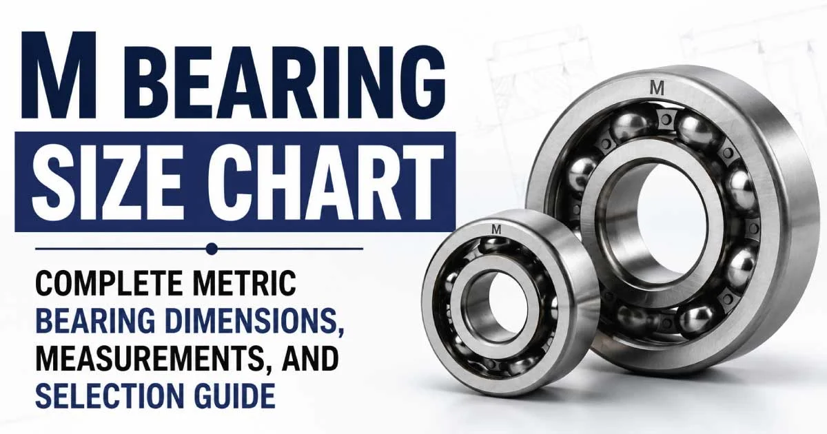
Metric bearings are commonly identified by their bore diameter, outside diameter, and width. If you are replacing a worn bearing, selecting a bearing for a shaft, or checking equipment specifications, an M bearing size chart can help you identify the dimensions you need before purchasing a replacement.
However, the letter M does not identify one universal bearing size series across all manufacturers and applications. It may appear in a manufacturer’s designation, a product-specific series, or a drawing reference. The complete bearing number and applicable manufacturer’s catalog are therefore important when confirming dimensions.
This guide explains metric bearing dimensions, standard measurement methods, common bearing types, identification techniques, and selection considerations. It also provides a practical dimensional reference so you can compare bearings accurately without relying on the designation alone.
What Is an M Bearing Size Chart?
An M bearing size chart is a dimensional reference used to understand or identify bearings associated with an M-series designation or a particular manufacturer’s M-coded product range. The exact meaning depends on the bearing manufacturer and product family.
In general, metric bearing dimensions are expressed in millimeters (mm). Three measurements are especially important:
- Bore diameter (d): The inside diameter of the bearing, where the shaft fits.
- Outside diameter (D): The diameter across the outer ring.
- Width (B): The axial width of the bearing, measured from one side face to the other.
These dimensions are often written as d×D×Bd \times D \times Bd×D×B.
For example, a bearing measuring 20 × 47 × 14 mm has a nominal 20 mm bore, a 47 mm outside diameter, and a 14 mm width. These dimensions describe its basic envelope, not every feature needed to confirm interchangeability.
A complete identification may also require the bearing series, seal type, internal clearance, precision class, cage design, and load rating.
Why Bearing Dimensions Matter
Correct dimensions help ensure that the bearing fits its housing and shaft. An incorrect size may prevent installation, create excessive clearance, or cause the assembly to operate improperly.
A dimensional chart is useful for:
- Replacing worn or damaged bearings.
- Matching a bearing to an existing shaft and housing.
- Comparing products from different manufacturers.
- Identifying bearings when markings are partially worn.
- Planning maintenance for motors, pumps, gearboxes, and industrial machinery.
Metric Bearing Dimensions Explained
Before using a bearing chart, understand what each dimension measures and how it affects the installation.
Bore Diameter (d)
The bore is the central opening through which the shaft passes. It is one of the most important dimensions when choosing a replacement.
A bearing with a 25 mm bore is designed around a nominal 25 mm shaft interface, although the actual shaft diameter, fit tolerance, and operating conditions determine the correct fit.
The bore should not be confused with the shaft’s measured diameter under every operating condition. Temperature, load, shaft tolerance, and mounting requirements can influence the required fit.
Outside Diameter (D)
The outside diameter is measured across the outer ring. It determines whether the bearing fits into its housing or mounting location.
If the outside diameter is too large, the bearing may not fit. If it is too small, the housing may not support the bearing correctly unless the assembly is specifically designed for that arrangement.
Bearing Width (B)
Width is measured parallel to the shaft axis. It affects the space the bearing occupies and its position relative to adjacent components.
A bearing with the correct bore and outside diameter can still be incompatible if its width differs from the original bearing.
Other Important Bearing Specifications
| Specification | Symbol or notation | What it means |
|---|---|---|
| Bore diameter | ddd | Inside diameter |
| Outside diameter | DDD | Outside diameter of the outer ring |
| Width | BBB or TTT | Axial width, depending on bearing type |
| Dynamic load rating | CCC | Reference rating for dynamic loading |
| Static load rating | C0C_0C0 | Reference rating for static loading |
| Internal clearance | C2, CN, C3, etc. | Designated internal clearance group |
| Seal or shield | 2RS, ZZ, etc. | Protection and closure arrangement, subject to manufacturer conventions |
The symbols and suffix meanings can vary by bearing type and manufacturer. Always consult the applicable catalog when interpreting a complete bearing designation.
Metric Bearing Size Chart: Common Bearing Dimensions
Because “M bearing” is not a universal dimensional series, the following tables provide a practical reference for commonly used metric deep groove ball bearings. These are established bearing designations with nominal dimensions in millimeters, rather than a claim that every listed model belongs to an M series.
The tables cover the 6000, 6200, and 6300 series. Confirm the exact designation and manufacturer’s catalog before ordering a replacement.
6000 Series Bearing Dimensions
The 6000 series uses a relatively compact cross-section. It is useful where radial space is limited and the bearing’s load and speed requirements suit the lighter design.
| Bearing number | Bore d (mm) | Outside diameter D (mm) | Width B (mm) |
|---|---|---|---|
| 6000 | 10 | 26 | 8 |
| 6001 | 12 | 28 | 8 |
| 6002 | 15 | 32 | 9 |
| 6003 | 17 | 35 | 10 |
| 6004 | 20 | 42 | 12 |
| 6005 | 25 | 47 | 12 |
| 6006 | 30 | 55 | 13 |
| 6007 | 35 | 62 | 14 |
| 6008 | 40 | 68 | 15 |
| 6009 | 45 | 75 | 16 |
| 6010 | 50 | 80 | 16 |
Source: Published metric bearing dimension tables. Values are nominal boundary dimensions.
6200 Series Bearing Dimensions
The 6200 series is a widely used light-section deep groove ball bearing series. It is found in many electric motors, fans, pumps, and general-purpose machines.
| Bearing number | Bore d (mm) | Outside diameter D (mm) | Width B (mm) |
|---|---|---|---|
| 6200 | 10 | 30 | 9 |
| 6201 | 12 | 32 | 10 |
| 6202 | 15 | 35 | 11 |
| 6203 | 17 | 40 | 12 |
| 6204 | 20 | 47 | 14 |
| 6205 | 25 | 52 | 15 |
| 6206 | 30 | 62 | 16 |
| 6207 | 35 | 72 | 17 |
| 6208 | 40 | 80 | 18 |
| 6209 | 45 | 85 | 19 |
| 6210 | 50 | 90 | 20 |
Source: Metric bearing catalogs and dimensional references.
6300 Series Bearing Dimensions
The 6300 series generally has a heavier cross-section than the 6200 series at the same bore size. It may be appropriate where greater load capacity is needed and the available housing space permits the larger dimensions.
| Bearing number | Bore d (mm) | Outside diameter D (mm) | Width B (mm) |
|---|---|---|---|
| 6300 | 10 | 35 | 11 |
| 6301 | 12 | 37 | 12 |
| 6302 | 15 | 42 | 13 |
| 6303 | 17 | 47 | 14 |
| 6304 | 20 | 52 | 15 |
| 6305 | 25 | 62 | 17 |
| 6306 | 30 | 72 | 19 |
| 6307 | 35 | 80 | 21 |
| 6308 | 40 | 90 | 23 |
| 6309 | 45 | 100 | 25 |
| 6310 | 50 | 110 | 27 |
Source: Metric deep groove ball bearing dimension references.
Important: These are three separate bearing series, not interchangeable sizes. For example, a 6205 and 6305 both have a 25 mm bore, but their outside diameters and widths differ. You cannot substitute one for the other solely because the shaft diameter matches.
What Does the Letter M Mean in a Bearing Number?
One important detail can prevent a costly ordering mistake: M may describe a bearing’s cage rather than its dimensions.
Bearing designation systems use prefixes and suffixes to identify construction details. In some major manufacturers’ systems, the suffix M identifies a machined brass cage. However, its precise meaning and placement depend on the manufacturer and bearing family.
For example, a designation ending in M may indicate a cage design while the numerical portion identifies the bearing’s basic size and series. That does not mean all bearings with M in their markings share the same dimensions.
Bearing Markings to Check
| Marking or feature | Typical significance |
|---|---|
| Main numerical designation | Bearing type, dimension series, and bore code, depending on the numbering system |
| M | May identify a machined brass cage in certain manufacturer systems |
| ZZ or 2Z | Commonly indicates metal shields; exact notation varies |
| 2RS | Commonly indicates seals on both sides; construction varies by maker |
| C3 | Greater-than-normal internal clearance |
| C4 | Greater internal clearance than C3 |
| P5 or P6 | Precision-class designations in relevant systems |
These are common examples, not a universal suffix dictionary. A marking may have a different meaning in a specialized product family. Consult the manufacturer’s designation guide before interpreting an unfamiliar code.
Why the M Suffix Matters
A cage separates and guides rolling elements. Its design and material can affect operating behavior, suitability for particular speeds, lubrication requirements, and operating conditions.
When replacing a bearing marked with M, check both its basic dimensions and the specified cage construction. A bearing with matching dimensions but a different cage may not be a suitable substitute for every application.
Also Read:
Common Types of Metric Bearings
An M marking alone does not establish the bearing type. Before selecting a replacement, identify whether the application uses a ball bearing, roller bearing, or another design.
Deep Groove Ball Bearings:
These use balls running in deep raceway grooves. They primarily support radial loads and can also accommodate axial loads in both directions within their design limits. Common applications include electric motors, fans, pumps, and appliances.
Cylindrical Roller Bearings
These use cylindrical rolling elements and are suited to substantial radial loads. Axial-load capability depends on the bearing design. They are commonly used in gearboxes and industrial machinery.
Tapered Roller Bearings
Their tapered rollers and raceways allow them to support combined radial and axial loads. They are used in wheel hubs, vehicle drivetrains, and machinery requiring appropriate axial positioning.
Angular Contact Ball Bearings
These are designed for combined radial and axial loading, with axial capacity dependent on contact angle and arrangement. They are common in machine-tool spindles, pumps, and precision assemblies.
The dimensions of these bearing types are not necessarily described by the same width symbol or designation rules. A deep groove ball bearing chart should not be used to identify a tapered roller bearing simply because both have a metric bore.
How to Measure a Bearing Correctly
If the bearing number is missing or unreadable, measuring the existing bearing can help narrow down the options. Use a clean bearing and a suitable measuring instrument, such as a vernier caliper or micrometer.
Step 1: Measure the Bore Diameter
Measure across the inside opening of the inner ring. Keep the instrument square to the bore and avoid measuring at an angle.
Record the result in millimeters. If the bearing is worn, damaged, or distorted, the measured value may not represent its original nominal dimension.
Step 2: Measure the Outside Diameter
Position the measuring jaws across the outer ring’s widest diameter. Avoid measuring over projecting seals, shields, or unrelated features.
Take more than one measurement at different orientations if you suspect damage or deformation.
Step 3: Measure the Width
Measure the distance between the bearing’s two side faces, parallel to the shaft axis. Ensure the caliper contacts the actual bearing faces rather than a projecting seal or shaft component.
Step 4: Record the Full Designation
Look for numbers and letters etched or printed on the ring. Record the manufacturer, complete bearing number, suffixes, and any packaging details.
The marking can reveal information that three measurements cannot, including internal clearance, cage material, sealing arrangement, and precision class.
Step 5: Verify the Dimensions Against a Catalog
Compare the measured dimensions with the manufacturer’s dimensional table. If several bearing numbers have the same bore, compare their outside diameters, widths, and construction.
Measurement tip: Calipers are useful for initial identification, but they are not a substitute for checking the required shaft and housing tolerances. Precision applications may require more suitable instruments and specified measurement procedures.
How to Choose the Correct Metric Bearing Size
Choosing a bearing requires more than matching the three main dimensions. The replacement must also suit the loads, speed, temperature, lubrication, and mounting arrangement.
1. Match the Original Dimensions
Start with the complete original bearing number, if available. Verify the bore, outside diameter, and width.
Do not assume that bearings with the same bore are interchangeable. The 6000, 6200, and 6300 series illustrate how the same shaft size can correspond to different outside diameters and widths.
2. Evaluate the Load
Determine whether the bearing will support primarily radial loads, axial loads, or a combination of both.
- Radial loads act perpendicular to the shaft axis.
- Axial loads act parallel to the shaft axis.
- Combined loads include both directions.
Select a bearing whose load ratings and arrangement are suitable for the application. A larger bearing is not automatically the right choice if the housing or shaft cannot accommodate it.
3. Check Operating Speed
Bearing speed limits depend on bearing design, cage, lubrication, sealing, load, and operating conditions. A speed rating from one manufacturer should not automatically be applied to another product with different construction.
Use the specific manufacturer’s speed recommendations and account for the actual operating environment.
4. Consider Seals and Shields
Seals and shields help protect rolling elements and lubricant from contamination, but their behavior differs.
- Open bearings: Provide access to the internal components and typically rely on the surrounding assembly for protection.
- Shielded bearings: Use metal shields to help limit contamination and retain lubricant.
- Sealed bearings: Use sealing elements to provide greater protection against contaminants, depending on seal design.
Choose the closure arrangement based on contamination, friction, speed, temperature, and lubrication requirements.
5. Verify Internal Clearance and Fit
Internal clearance is the movement available between the bearing’s rolling elements and raceways before installation and under specified conditions.
A tight interference fit can reduce operating clearance. Heat can also change clearance during operation. Consequently, the original clearance designation may be important when replacing a motor or other continuously operated equipment bearing.
Shaft and housing fits should be selected according to load direction, material, temperature, and the manufacturer’s recommendations.
Also Read:
Common Bearing Size Identification Mistakes
Incorrect identification can lead to repeated failures, poor fit, or unnecessary equipment downtime.
| Common mistake | Why it causes problems | Better approach |
|---|---|---|
| Matching only the bore | Outside diameter or width may differ | Compare all three dimensions |
| Treating M as a universal size series | M may describe a cage or another manufacturer-specific feature | Verify the complete designation |
| Ignoring seals and shields | The replacement may have different protection or friction characteristics | Check the suffix and closure type |
| Guessing from appearance | Similar-looking bearings can have different dimensions | Measure and consult a catalog |
| Ignoring internal clearance | The bearing may not operate correctly after installation | Match the required clearance specification |
| Choosing by size alone | Load, speed, and temperature requirements may be unsuitable | Verify the operating ratings |
Never force a bearing into a housing or onto a shaft simply because its dimensions appear close. Forcing an incorrect fit can damage the rings, rolling elements, or mating components.
Bearing Size Conversion: Millimeters to Inches
Metric bearing dimensions are sometimes compared with inch-based components. To convert a measurement from millimeters to inches, divide the millimeter value by 25.4.
Inches=Millimeters25.4\text{Inches}=\frac{\text{Millimeters}}{25.4}Inches=25.4Millimeters
The following table gives approximate conversions for commonly encountered metric dimensions.
| Metric (mm) | Inches (approx.) |
|---|---|
| 10 | 0.3937 |
| 12 | 0.4724 |
| 15 | 0.5906 |
| 17 | 0.6693 |
| 20 | 0.7874 |
| 25 | 0.9843 |
| 30 | 1.1811 |
| 40 | 1.5748 |
| 50 | 1.9685 |
These conversions are useful for comparison, but they do not establish that a metric bearing and an inch-series bearing are interchangeable. Confirm the original nominal dimensions, tolerances, and bearing designation before ordering.
Also Read:
Frequently Asked Questions
What does M mean on a bearing?
In some bearing designation systems, M identifies a machined brass cage. However, its meaning depends on the manufacturer and bearing family. Check the complete bearing number and manufacturer’s catalog rather than assuming M identifies a particular size.
How do I find the correct M bearing size?
Start by recording the complete bearing designation. If the marking is unavailable, measure the bore diameter, outside diameter, and width. Then compare those measurements with the appropriate manufacturer’s catalog and verify the required construction and operating specifications.
What are the three main bearing dimensions?
The three main dimensions are bore diameter (ddd), outside diameter (DDD), and width (BBB). They are generally expressed in millimeters for metric bearings.
Are 6000, 6200, and 6300 bearings interchangeable?
No, not automatically. Bearings in these series may share a bore diameter while having different outside diameters and widths. Their load capacities and other operating characteristics can also differ.
What is the difference between a sealed and a shielded bearing?
A sealed bearing uses sealing elements to help restrict contamination and lubricant leakage. A shielded bearing uses shields, commonly metal, to provide a different level of protection. The appropriate choice depends on the environment, speed, friction, and lubrication requirements.
Can I replace a bearing using measurements alone?
Measurements can identify likely candidates, but they may not reveal internal clearance, cage construction, precision class, or load ratings. For critical machinery, verify the full designation and specifications before installing a replacement.
Where can I find an accurate bearing dimension chart?
Consult the catalog from the original bearing manufacturer or a recognized bearing supplier. Published dimensional references, such as those covering the 6000, 6200, and 6300 series, can help with initial identification.
Conclusion
An accurate M bearing size chart helps with bearing identification, but the letter M alone does not define a universal metric size. Check the complete designation, measure the bore, outside diameter, and width, and confirm the bearing’s construction and operating requirements.
The 6000, 6200, and 6300 series charts provide a useful starting point for common metric deep groove ball bearings. For a reliable replacement, always verify the original bearing specifications against the manufacturer’s catalog before purchasing or installing the part.