
Choosing the right coaxial cable requires more than knowing whether the cable is called RG6, RG59, or RG11. Cable size, construction, impedance, frequency range, length, and signal loss can all affect whether a cable is suitable for a particular installation.
A coaxial cable size chart makes it easier to compare common cable types and understand how their physical dimensions relate to typical applications. However, the term “size” can be confusing because coaxial cable designations such as RG6 and RG59 identify cable families rather than simply describing one universal outside diameter.
This guide explains common coaxial cable types, how coaxial cable sizes are identified, what causes signal loss, how cable length affects performance, and how to choose the right cable for TV, satellite, CCTV, networking, radio, and other applications.
What Is a Coaxial Cable?
A coaxial cable is an electrical cable designed to carry high-frequency signals while providing shielding against electromagnetic interference.
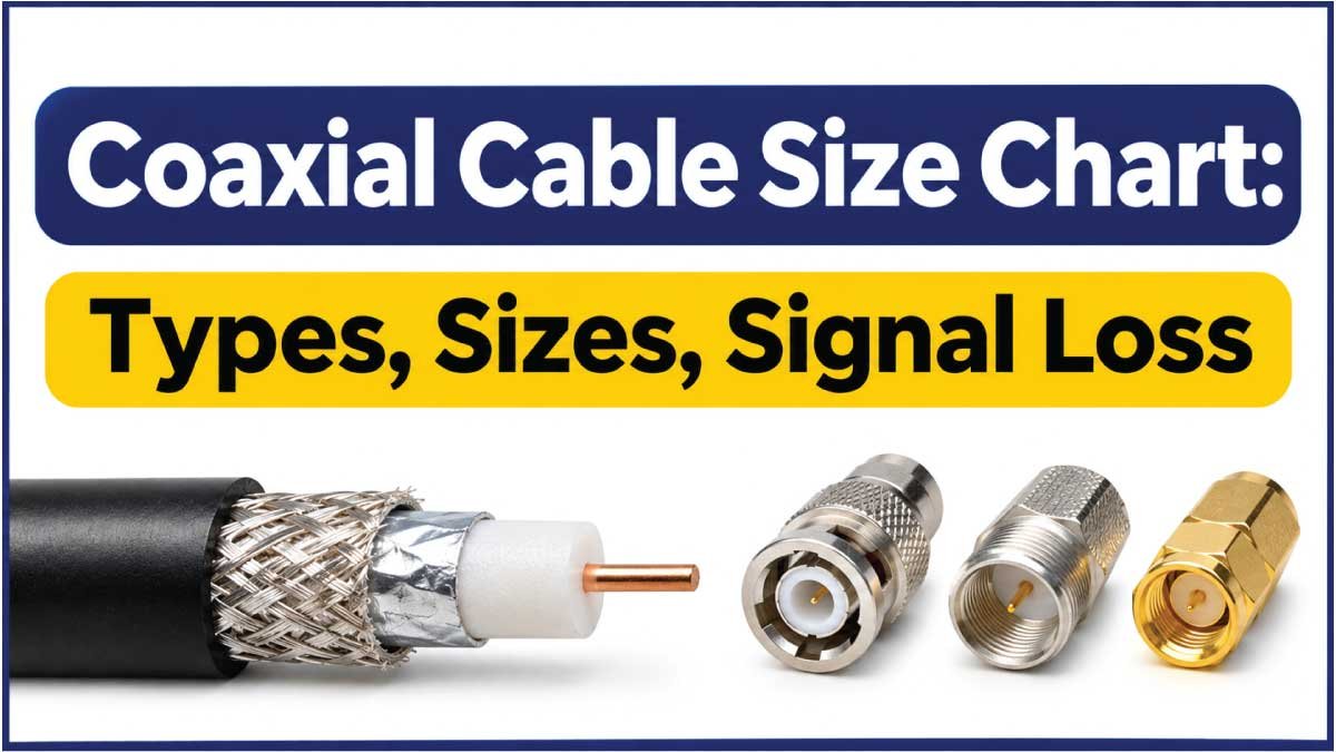
Its construction normally includes several layers arranged around a common center axis:
- Center conductor: Carries the electrical signal.
- Dielectric insulator: Separates the conductor from the shield.
- Shield: Helps contain the signal and reduce interference.
- Outer jacket: Protects the cable from physical and environmental damage.
This layered construction is what gives coaxial cable its name. The center conductor and surrounding shield share the same axis.
Coaxial cables are widely used for:
- Television signals
- Cable internet
- Satellite TV
- CCTV systems
- Radio-frequency equipment
- Antenna connections
- Broadband communications
- Test and measurement equipment
Different applications require different cable characteristics, so there is no single coaxial cable size that is best for every installation.
Coaxial Cable Size Chart
The following chart compares several commonly encountered coaxial cable types. Exact outside dimensions can vary between manufacturers and constructions, so the chart should be used as a general comparison rather than a universal dimensional specification.
| Cable Type | General Size Category | Common Impedance | Typical Applications |
|---|---|---|---|
| RG58 | Small | 50 Ω | RF, radio, instrumentation |
| RG59 | Small to medium | 75 Ω | CCTV, video, legacy video systems |
| RG6 | Medium | 75 Ω | TV, satellite, cable internet |
| RG11 | Large | 75 Ω | Longer TV and broadband runs |
| RG213 | Large | 50 Ω | RF and communications |
| LMR-400 class | Large | 50 Ω | RF, antennas, wireless systems |
The important point is that RG designations do not by themselves provide an exact physical diameter. Different manufacturers can produce cables within the same general family using different jackets, shields, dielectric materials, and construction methods.
Always check the manufacturer’s dimensional specification when physical fit is important.
Common Coaxial Cable Types
Different coaxial cable families are designed around different electrical and mechanical requirements.
RG58 Coaxial Cable
RG58 is commonly associated with 50-ohm RF applications.
It is relatively flexible compared with many larger coaxial cables, making it useful where cable routing and connector installation are important.
Typical applications include:
- RF equipment
- Amateur radio
- Test equipment
- Antenna connections
- Communications equipment
RG58 should not automatically be substituted for a 75-ohm cable simply because the physical size appears similar. Impedance is a critical part of coaxial cable selection.
RG59 Coaxial Cable
RG59 is commonly associated with 75-ohm video applications.
It has traditionally been used for applications such as:
- CCTV
- Analog video
- Video distribution
- Older television systems
Its relatively smaller construction can make it easier to route than larger 75-ohm cable types.
However, for modern broadband, satellite, and many higher-frequency installations, another cable type may be more appropriate.
RG6 Coaxial Cable
RG6 is one of the most common 75-ohm coaxial cable types used in residential installations.
Common applications include:
- Cable television
- Satellite television
- Over-the-air antenna systems
- Cable modem connections
- Broadband distribution
- Home video systems
RG6 generally has a larger conductor and thicker overall construction than RG59, although exact dimensions depend on the manufacturer and cable design.
RG11 Coaxial Cable
RG11 is a larger 75-ohm coaxial cable commonly considered when longer cable runs require lower attenuation than smaller cable constructions can provide.
Its larger physical size also makes it:
- Less flexible
- More difficult to route
- More demanding to terminate
- Less convenient in tight spaces
For long installations, however, its electrical characteristics can make it useful where signal loss is a major consideration.
50-Ohm vs 75-Ohm Coaxial Cable
One of the most important differences between coaxial cables is characteristic impedance.
The two values encountered most often are:
- 50 ohms (Ω)
- 75 ohms (Ω)
They are not simply different physical sizes.
50-Ohm Coax
50-ohm coaxial cables are commonly used for RF transmission applications such as:
- Radio equipment
- Wireless systems
- RF test equipment
- Antenna systems
- Communications equipment
75-Ohm Coax
75-ohm coaxial cables are commonly used for:
- Television
- Satellite systems
- Video distribution
- Cable broadband
- Many residential antenna systems
Using the correct impedance helps ensure that the cable matches the equipment and system design.
For this reason, selecting a cable based only on its outside diameter can lead to an incorrect choice.
Coaxial Cable Size vs Cable Diameter
When people search for a coaxial cable size chart, they may actually be looking for one of several different measurements.
“Size” can refer to:
- Overall cable diameter
- Center conductor diameter
- Dielectric dimensions
- Shield construction
- Characteristic impedance
- Cable family or designation
- Connector size
- Electrical performance
For physical installation, overall outside diameter is often the most important measurement because it determines whether the cable can fit through a hole, conduit, connector, or cable gland.
For electrical performance, however, diameter alone is not enough.
A larger cable may offer lower attenuation for a particular design, but the result depends on conductor material, dielectric, shielding, operating frequency, and construction.
Coaxial Cable Signal Loss Explained
Signal loss is one of the most important factors when selecting coaxial cable.
It is commonly expressed in decibels (dB) and often specified as attenuation over a particular length at a particular frequency.
For example, a manufacturer’s specification might provide attenuation in a form such as:
dB per 100 ft at a specified frequency
or
dB per 100 m at a specified frequency.
This is important because coaxial cable does not have one fixed signal-loss value.
Frequency Matters
Signal attenuation generally increases as operating frequency increases.
A cable might therefore have relatively low attenuation at one frequency and significantly higher attenuation at another.
This is why a useful cable specification should identify:
- Frequency
- Cable length
- Attenuation
- Cable construction
- Temperature or environmental conditions when relevant
Simply saying that one cable has “low loss” is not enough to determine whether it is suitable for a specific application.
How Cable Length Affects Signal Loss
As coaxial cable length increases, total signal attenuation generally increases.
This means a short cable and a long cable made from the same cable type will not necessarily deliver the same signal level at the receiving equipment.
A simple way to understand the relationship is:
Total cable loss = attenuation per unit length × cable length
For example, if a manufacturer provides an attenuation value per 100 feet, doubling the cable length will approximately double the cable contribution to attenuation under the same conditions.
Real installations can also introduce additional losses from:
- Connectors
- Adapters
- Splitters
- Couplers
- Poor terminations
- Bends
- Damaged cable
- Impedance mismatches
Therefore, the cable itself is not always the only source of signal loss.
RG59 vs RG6
RG59 and RG6 are both associated with 75-ohm systems, but they are not identical.
| Feature | RG59 | RG6 |
|---|---|---|
| General impedance | 75 Ω | 75 Ω |
| General construction | Smaller | Larger |
| Typical use | Video and CCTV | TV, satellite, broadband |
| Flexibility | Generally more flexible | Generally less flexible |
| Long-run suitability | Application dependent | Commonly preferred for many modern distribution systems |
| High-frequency applications | More limited depending on construction | Commonly better suited |
| Typical residential TV use | Older installations | Very common |
The correct choice depends on the frequency, distance, connectors, and equipment.
For many modern residential TV and broadband applications, RG6 is a common choice. RG59 can still be useful for suitable video applications where its characteristics meet the system requirements.
Also Read:
RG6 vs RG11
Both RG6 and RG11 are commonly associated with 75-ohm applications, but their physical characteristics are different.
| Feature | RG6 | RG11 |
|---|---|---|
| Physical size | Medium | Larger |
| Flexibility | Better | Lower |
| Installation difficulty | Easier | More demanding |
| Typical residential use | Very common | More specialized |
| Longer cable runs | Suitable for many installations | Often considered for longer runs |
| Space requirements | Lower | Higher |
RG11 can be useful when reducing attenuation over longer runs is important, but its larger size can make installation more difficult.
For a typical home installation, RG6 may be more practical unless the system’s distance and signal requirements justify a larger cable.
Coaxial Cable Size and Frequency
Cable selection should always consider operating frequency.
A cable designed for relatively low-frequency applications may not provide the same performance at much higher frequencies.
For RF applications, manufacturers commonly provide attenuation specifications across a range of frequencies.
When comparing two cables, look for a table that provides:
- Frequency in MHz or GHz
- Attenuation in dB per specified length
- Maximum operating frequency
- Impedance
- Velocity factor when required
- Power-handling information when relevant
This information is much more useful than simply comparing the physical thickness of the cables.
Also Read:
How to Choose the Right Coaxial Cable
The best coaxial cable depends on the equipment and installation.
1. Check the Impedance
First determine whether the system requires 50 Ω or 75 Ω coax.
Do not assume that cables with similar dimensions are interchangeable.
2. Check the Frequency
Determine the highest frequency that the cable must carry.
A cable suitable for one frequency range may have unacceptable attenuation at another.
3. Measure the Required Length
Calculate the complete cable route rather than simply estimating the distance between the two devices.
Include the path around walls, equipment, racks, ceilings, or conduits.
4. Compare Attenuation
For longer runs, compare manufacturer attenuation specifications at the frequency used by your system.
Lower attenuation can be especially important when the available signal level is limited.
5. Check the Physical Diameter
Make sure the cable can physically fit through:
- Conduit
- Wall openings
- Cable glands
- Connector bodies
- Equipment spaces
6. Check Connector Compatibility
The cable must be compatible with the connectors used by the equipment.
Common coaxial connector types include:
- F connectors
- BNC
- N-type
- SMA
- TNC
- UHF connectors
The connector must match both the cable construction and the equipment requirements.
Also Read:
Common Coaxial Cable Problems
Poor performance does not always mean that the wrong cable size was selected.
Common problems include:
- Excessive cable length
- Damaged outer jacket
- Poor connector installation
- Loose connectors
- Incorrect impedance
- Improper cable termination
- Excessive bending
- Poor-quality splitters
- Water entering outdoor cable
- Using a cable outside its intended frequency range
A properly selected cable can still perform poorly if the installation is damaged or incorrectly terminated.
How to Reduce Coaxial Cable Signal Loss
If signal loss is becoming a problem, start with the installation rather than immediately replacing every component.
Use the Correct Cable
Choose a cable whose electrical characteristics match the application.
Keep Runs Reasonably Short
Avoid unnecessary cable length.
Use Quality Connectors
Poor connectors can add loss and create intermittent connections.
Minimize Unnecessary Connections
Every connector, adapter, splitter, and coupler can introduce additional loss.
Avoid Sharp Bends
Follow the cable manufacturer’s recommended minimum bend radius.
A sharp bend can damage the cable structure and affect performance.
Protect Outdoor Cable
Outdoor coaxial cable should be suitable for the environment and protected against moisture and physical damage.
Coaxial Cable Selection by Application
The following table provides a general starting point.
| Application | Common Cable Type | Typical Impedance |
|---|---|---|
| Cable TV | RG6 | 75 Ω |
| Satellite TV | RG6 | 75 Ω |
| Home antenna | RG6 | 75 Ω |
| Cable modem | RG6 | 75 Ω |
| CCTV/video | RG59 or application-specific coax | 75 Ω |
| RF communications | RG58 or other RF coax | 50 Ω |
| Larger RF installations | Application-specific low-loss coax | Often 50 Ω |
This table is intended as a general guide. The equipment documentation should take priority when it specifies a particular cable type.
Frequently Asked Questions
What is the most common coaxial cable size?
There is no single universal coaxial cable size. RG6 is one of the most commonly encountered 75-ohm coaxial cable types for residential TV, satellite, antenna, and broadband applications.
What is the difference between RG6 and RG59?
Both are commonly used as 75-ohm coaxial cable types, but RG6 generally has a larger construction and is widely used for modern TV, satellite, and broadband installations. RG59 is commonly associated with video and older CCTV applications.
Does thicker coaxial cable have less signal loss?
Not automatically. Cable diameter can influence electrical performance, but signal loss depends on the complete cable design, including conductor, dielectric, shielding, frequency, and construction.
What causes coaxial cable signal loss?
Signal loss can result from cable length, operating frequency, cable construction, connectors, splitters, adapters, poor terminations, and damaged or improperly installed cable.
Is RG6 better than RG59?
Neither is universally better. RG6 is commonly preferred for many modern TV, satellite, and broadband applications, while RG59 can be appropriate for certain video applications. The correct choice depends on the system.
What does 50-ohm coaxial cable mean?
50 ohms is the cable’s characteristic impedance. 50-ohm coax is widely used in RF and communications systems.
What does 75-ohm coaxial cable mean?
75 ohms is the cable’s characteristic impedance. 75-ohm coax is widely used for television, video, satellite, antenna, and broadband distribution.
Does longer coaxial cable reduce signal strength?
Longer cable runs generally introduce more attenuation. The amount of loss depends on the cable’s attenuation characteristics and the frequency being transmitted.
Can I use RG6 instead of RG59?
It depends on the application and physical installation. Both are commonly 75-ohm cables, but their construction and electrical characteristics differ. The equipment and system requirements should be checked before substitution.
How do I calculate coaxial cable loss?
Use the manufacturer’s attenuation specification for the operating frequency and multiply the attenuation per unit length by the cable length. Then account for additional losses from connectors, splitters, and other components.
Conclusion
A coaxial cable size chart is useful for comparing common cable families, but physical size alone does not determine cable performance. Impedance, frequency, construction, attenuation, length, connectors, and installation conditions all matter.
RG59, RG6, and RG11 are commonly associated with 75-ohm systems, while RG58 and many other RF cable types are commonly associated with 50-ohm applications. The appropriate choice depends on the equipment and signal rather than simply selecting the thickest or largest cable.
When signal loss is important, check the manufacturer’s attenuation specifications at the actual operating frequency. Keep unnecessary cable length and connections to a minimum, use compatible connectors, and protect the cable from damage and environmental exposure.
The best coaxial cable is therefore not necessarily the biggest one. It is the cable whose electrical characteristics, physical dimensions, length, and construction match the requirements of the system.