
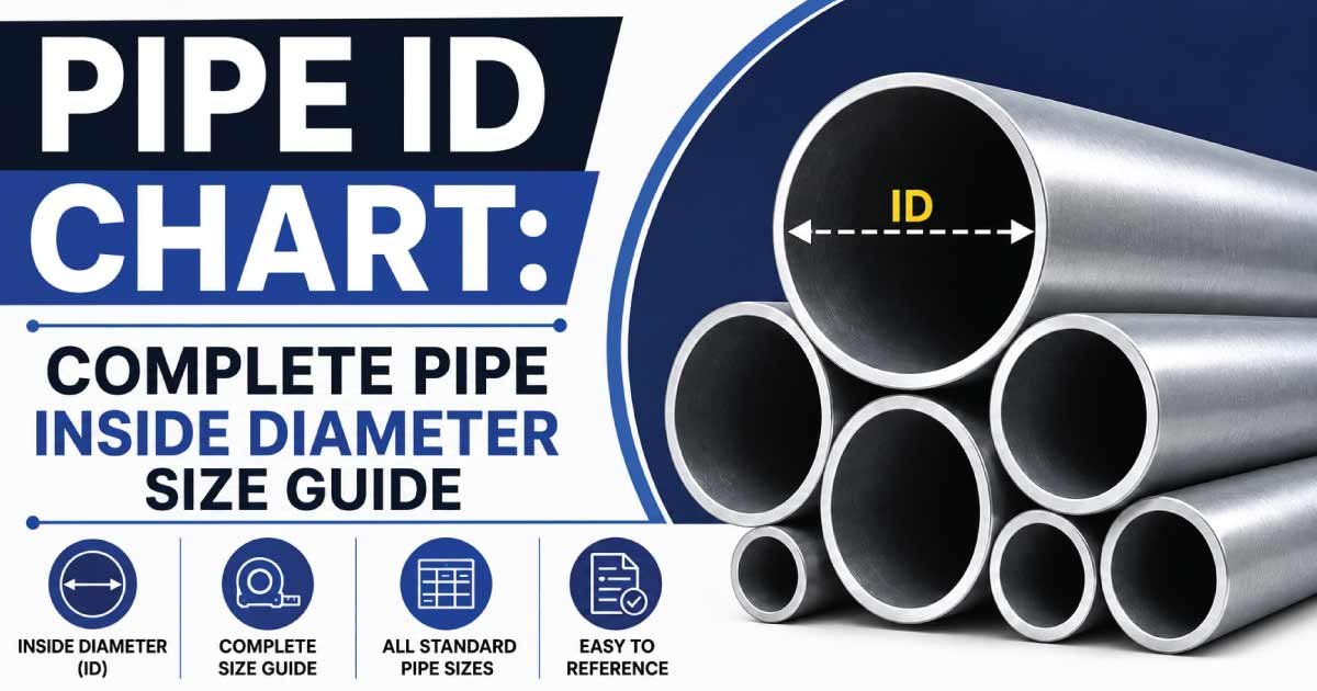
The inside diameter of a pipe is one of the most important dimensions to understand when selecting pipe, calculating flow capacity, identifying pipe sizes, and designing piping systems. Unlike nominal pipe size, the inside diameter (ID) can change when the pipe wall thickness changes.
For this reason, two pipes with the same nominal size can have different inside diameters when they have different schedules or wall thicknesses.
For example, a standard 2-inch pipe has an outside diameter of approximately 2.375 inches, but its inside diameter depends on the wall thickness. A thinner-wall pipe has a larger ID, while a thicker-wall pipe has a smaller ID.
This complete guide explains pipe inside diameter, nominal pipe size, outside diameter, wall thickness, pipe schedules, common ID values, metric conversions, calculation methods, and how to identify an unknown pipe.
What Is Pipe Inside Diameter?
Inside diameter, abbreviated as ID, is the distance measured across the inside of a round pipe from one internal wall to the opposite internal wall.
It represents the approximate open passage available for fluid, gas, or another material moving through the pipe.
Pipe ID is important because it directly affects:
- Flow area
- Fluid velocity
- Pressure loss
- Flow capacity
- Internal volume
- Pump requirements
- Pipe identification
- Fitting selection
- Process-system design
Unlike outside diameter, the inside diameter is not always a fixed value for a particular nominal pipe size.
The ID changes according to the pipe’s wall thickness.
Pipe ID Chart
The following table provides approximate inside diameters for common nominal pipe sizes using commonly encountered Schedule 40 dimensions.
| Nominal Pipe Size | OD (in) | Wall Thickness (in) | Approx. ID (in) | Approx. ID (mm) |
|---|---|---|---|---|
| 1/8″ | 0.405 | 0.068 | 0.269 | 6.8 |
| 1/4″ | 0.540 | 0.088 | 0.364 | 9.2 |
| 3/8″ | 0.675 | 0.091 | 0.493 | 12.5 |
| 1/2″ | 0.840 | 0.109 | 0.622 | 15.8 |
| 3/4″ | 1.050 | 0.113 | 0.824 | 20.9 |
| 1″ | 1.315 | 0.133 | 1.049 | 26.6 |
| 1-1/4″ | 1.660 | 0.140 | 1.380 | 35.1 |
| 1-1/2″ | 1.900 | 0.145 | 1.610 | 40.9 |
| 2″ | 2.375 | 0.154 | 2.067 | 52.5 |
| 2-1/2″ | 2.875 | 0.203 | 2.469 | 62.7 |
| 3″ | 3.500 | 0.216 | 3.068 | 77.9 |
| 3-1/2″ | 4.000 | 0.226 | 3.548 | 90.1 |
| 4″ | 4.500 | 0.237 | 4.026 | 102.3 |
| 5″ | 5.563 | 0.258 | 5.047 | 128.2 |
| 6″ | 6.625 | 0.280 | 6.065 | 154.1 |
| 8″ | 8.625 | 0.322 | 7.981 | 202.7 |
| 10″ | 10.750 | 0.365 | 10.020 | 254.5 |
| 12″ | 12.750 | 0.375 | 12.000 | 304.8 |
Note: These are common Schedule 40 reference values. Actual dimensions and allowable tolerances should be verified against the applicable pipe standard for engineering or fabrication work.
Why Pipe ID Is Important
Pipe ID determines the amount of open space available inside the pipe.
A larger ID generally provides a larger flow area, while a smaller ID restricts the available passage.
For example, consider two pipes with the same nominal size and outside diameter:
- Pipe A has a thinner wall.
- Pipe B has a thicker wall.
Pipe A will have a larger inside diameter.
Pipe B will have a smaller inside diameter.
This difference can affect flow velocity and pressure loss.
Consequently, selecting pipe based only on nominal size can be misleading when the application depends on precise flow characteristics.
Nominal Pipe Size vs. Inside Diameter
Nominal Pipe Size (NPS) is a standardized designation and should not automatically be interpreted as the actual inside diameter.
For example, a:
2-inch nominal pipe
does not necessarily have a 2-inch ID.
A common Schedule 40 2-inch pipe has an ID of approximately:
2.067 inches
or:
52.5 mm
The nominal size is used to identify the pipe within the standard system, while the actual ID depends on the outside diameter and wall thickness.
Pipe ID Formula
The basic formula for calculating inside diameter is:
ID = OD − 2 × Wall Thickness
Where:
- ID = inside diameter
- OD = outside diameter
- Wall Thickness = thickness of one pipe wall
For example, suppose a pipe has:
OD = 2.375 inches
and:
Wall thickness = 0.154 inch
The calculation is:
ID = 2.375 − (2 × 0.154)
ID = 2.375 − 0.308
ID = 2.067 inches
Therefore, the approximate inside diameter is:
2.067 inches
Pipe ID in Inches and Millimeters
Pipe dimensions may be expressed in inches or millimeters.
The standard conversion is:
1 inch = 25.4 mm
For example:
2.067 × 25.4 = 52.50 mm
Therefore:
2.067 inches ≈ 52.5 mm
Common Pipe ID Conversions
| ID (in) | ID (mm) |
|---|---|
| 0.269 | 6.8 |
| 0.364 | 9.2 |
| 0.493 | 12.5 |
| 0.622 | 15.8 |
| 0.824 | 20.9 |
| 1.049 | 26.6 |
| 1.380 | 35.1 |
| 1.610 | 40.9 |
| 2.067 | 52.5 |
| 2.469 | 62.7 |
| 3.068 | 77.9 |
| 3.548 | 90.1 |
| 4.026 | 102.3 |
| 5.047 | 128.2 |
| 6.065 | 154.1 |
| 7.981 | 202.7 |
| 10.020 | 254.5 |
| 12.000 | 304.8 |
Pipe ID Chart for Common Sizes
| NPS | Schedule 40 Approx. ID |
|---|---|
| 1/2″ | 0.622″ |
| 3/4″ | 0.824″ |
| 1″ | 1.049″ |
| 1-1/4″ | 1.380″ |
| 1-1/2″ | 1.610″ |
| 2″ | 2.067″ |
| 2-1/2″ | 2.469″ |
| 3″ | 3.068″ |
| 3-1/2″ | 3.548″ |
| 4″ | 4.026″ |
| 5″ | 5.047″ |
| 6″ | 6.065″ |
| 8″ | 7.981″ |
| 10″ | 10.020″ |
| 12″ | 12.000″ |
This is a useful quick-reference table for common Schedule 40 pipe.
How Pipe Schedule Affects Inside Diameter
One of the most important concepts in pipe sizing is the relationship between schedule and inside diameter.
For a given nominal pipe size, different schedules generally have the same standardized outside diameter while using different wall thicknesses.
As wall thickness increases:
Inside diameter decreases.
As wall thickness decreases:
Inside diameter increases.
For example, a 2-inch pipe may be available in several wall thicknesses.
A lighter wall provides a larger internal passage.
A heavier wall provides a smaller internal passage.
Therefore, when someone asks for the “ID of a 2-inch pipe,” the schedule or actual wall thickness should also be identified.
2-Inch Pipe ID by Schedule
A 2-inch nominal pipe is a good example of how schedule changes ID.
| 2-Inch Pipe | Approx. Wall Thickness | Approx. ID |
|---|---|---|
| Schedule 10 | 0.065″ | 2.245″ |
| Schedule 40 | 0.154″ | 2.067″ |
| Schedule 80 | 0.218″ | 1.939″ |
| Schedule 160 | 0.343″ | 1.689″ |
The outside diameter remains approximately:
2.375 inches
The inside diameter changes because the wall thickness changes.
3-Inch Pipe ID by Schedule
| 3-Inch Pipe | Approx. Wall Thickness | Approx. ID |
|---|---|---|
| Schedule 10 | 0.120″ | 3.260″ |
| Schedule 40 | 0.216″ | 3.068″ |
| Schedule 80 | 0.300″ | 2.900″ |
| Schedule 160 | 0.437″ | 2.626″ |
This demonstrates why schedule must be considered when calculating internal flow space.
4-Inch Pipe ID by Schedule
| 4-Inch Pipe | Approx. Wall Thickness | Approx. ID |
|---|---|---|
| Schedule 10 | 0.120″ | 4.260″ |
| Schedule 40 | 0.237″ | 4.026″ |
| Schedule 80 | 0.337″ | 3.826″ |
| Schedule 160 | 0.531″ | 3.438″ |
The larger the wall thickness, the smaller the ID.
6-Inch Pipe ID by Schedule
| 6-Inch Pipe | Approx. Wall Thickness | Approx. ID |
|---|---|---|
| Schedule 10 | 0.134″ | 6.357″ |
| Schedule 40 | 0.280″ | 6.065″ |
| Schedule 80 | 0.432″ | 5.761″ |
| Schedule 160 | 0.718″ | 5.189″ |
Again, the nominal size and OD remain standardized while the internal opening changes.
8-Inch Pipe ID by Schedule
| 8-Inch Pipe | Approx. Wall Thickness | Approx. ID |
|---|---|---|
| Schedule 10 | 0.148″ | 8.329″ |
| Schedule 40 | 0.322″ | 7.981″ |
| Schedule 80 | 0.500″ | 7.625″ |
| Schedule 160 | 0.906″ | 6.813″ |
The difference becomes significant in larger pipes.
10-Inch Pipe ID by Schedule
| 10-Inch Pipe | Approx. Wall Thickness | Approx. ID |
|---|---|---|
| Schedule 10 | 0.165″ | 10.420″ |
| Schedule 40 | 0.365″ | 10.020″ |
| Schedule 80 | 0.500″ | 9.750″ |
| Schedule 160 | 1.000″ | 8.750″ |
A heavier wall can significantly reduce the internal opening.
12-Inch Pipe ID by Schedule
| 12-Inch Pipe | Approx. Wall Thickness | Approx. ID |
|---|---|---|
| Schedule 10 | 0.180″ | 12.390″ |
| Schedule 40 | 0.375″ | 12.000″ |
| Schedule 80 | 0.500″ | 11.750″ |
| Schedule 120 | 0.562″ | 11.626″ |
| Schedule 160 | 1.000″ | 10.750″ |
The exact schedule availability and dimensions should always be checked against the applicable standard.
Also Read:
Pipe ID and Flow Area
Inside diameter is directly related to the internal cross-sectional area of a round pipe.
The formula for cross-sectional area is:
A = πD² ÷ 4
Where:
- A = internal flow area
- D = inside diameter
Because diameter is squared, even a relatively small change in ID can produce a meaningful change in flow area.
For example, if the ID increases from 2 inches to 2.2 inches, the flow area does not increase by only 10%. The square relationship produces a larger change.
Why Pipe ID Matters for Flow
A pipe’s internal diameter affects the movement of liquids and gases.
Important factors include:
- Flow velocity
- Pressure drop
- Friction losses
- Pump requirements
- System capacity
- Reynolds number
- Flow regime
For a given volumetric flow rate, a smaller ID generally produces higher fluid velocity.
A larger ID generally produces lower velocity at the same flow rate.
This is why accurate pipe dimensions are important in hydraulic and process-system design.
Pipe ID and Fluid Velocity
The relationship between volumetric flow and velocity can be expressed as:
Q = A × V
Where:
- Q = volumetric flow rate
- A = internal flow area
- V = average fluid velocity
Therefore:
V = Q ÷ A
Since the area depends on the square of the inside diameter, changes in pipe ID can have a significant effect on velocity.
Engineers use these relationships when sizing piping systems.
Pipe ID and Pressure Loss
Pipe inside diameter also affects pressure loss due to friction.
For the same fluid and flow rate, reducing the pipe ID generally increases velocity and can increase friction-related pressure loss.
This is why pipe selection should not be based solely on nominal size.
Other factors include:
- Pipe material
- Internal roughness
- Fluid properties
- Flow rate
- Pipe length
- Fittings
- Valves
- Elevation
- Operating temperature
For a complete system calculation, appropriate engineering equations and design standards should be used.
Pipe ID vs. Pipe OD
Pipe ID and OD describe opposite sides of the pipe wall.
Outside Diameter:
Measurement across the outside of the pipe.
Inside Diameter:
Measurement across the open internal passage.
The relationship is:
OD − 2 × Wall Thickness = ID
For example:
OD = 4.500 inches
Wall = 0.237 inch
ID = 4.500 − 0.474
ID = 4.026 inches
Pipe ID vs. Nominal Size
Nominal pipe size is not always equal to the actual ID.
Consider these examples:
| NPS | Approx. Actual ID, Schedule 40 |
|---|---|
| 1/2″ | 0.622″ |
| 1″ | 1.049″ |
| 2″ | 2.067″ |
| 3″ | 3.068″ |
| 4″ | 4.026″ |
| 6″ | 6.065″ |
| 8″ | 7.981″ |
| 10″ | 10.020″ |
| 12″ | 12.000″ |
Some larger nominal sizes have IDs close to their nominal designation, but the values should still be treated as standardized dimensions rather than assumptions.
Pipe ID and Tubing
Pipe and tubing use different sizing conventions.
Pipe is commonly identified by nominal pipe size and wall thickness or schedule.
Tubing is frequently identified by:
- Actual outside diameter
- Wall thickness
For example, 2-inch tubing typically has an actual OD of approximately 2 inches, while 2-inch nominal pipe has an OD of approximately 2.375 inches.
Therefore, a 2-inch tube and a 2-inch nominal pipe are not necessarily interchangeable.
Pipe ID and Fitting Selection
Inside diameter is important for applications involving flow, but fitting compatibility involves additional dimensions.
When selecting fittings, consider:
- Nominal size
- Pipe standard
- OD
- ID
- Wall thickness
- Connection method
- Thread specification
- Material
- Pressure rating
- Temperature rating
For example, a fitting designed for a specific pipe standard should not be selected solely because its stated nominal size appears to match.
Also Read:
How to Measure Pipe Inside Diameter
There are several methods for measuring ID.
Using an Inside Caliper
For accessible pipe ends, an inside caliper can measure the internal diameter directly.
This is useful for smaller and medium-sized pipe.
Using a Telescoping Gauge
A telescoping gauge can be positioned inside the pipe and then measured with an outside micrometer or caliper.
Using Ultrasonic Measurement
For installed pipe or applications where access is limited, specialized ultrasonic equipment can sometimes estimate wall thickness and internal dimensions.
Using Known OD and Wall Thickness
If the OD and wall thickness are known:
ID = OD − 2 × Wall Thickness
This is often the simplest calculation.
How to Identify an Unknown Pipe by ID
If pipe markings are unavailable, measuring ID can help identify the pipe.
A practical identification process is:
Step 1: Measure the ID
Measure across the internal opening.
Step 2: Measure the OD
Measure the exterior diameter.
Step 3: Calculate Wall Thickness
Use:
Wall Thickness = (OD − ID) ÷ 2
Step 4: Compare With Standard Tables
Compare your measurements with standard pipe dimensions.
Step 5: Identify the Nominal Size and Schedule
Once the dimensions are close to a standard combination, verify the pipe standard and tolerance.
This approach is much more reliable than identifying pipe based on appearance alone.
Calculating Wall Thickness From ID and OD
If both ID and OD are known, wall thickness can be calculated.
The formula is:
Wall Thickness = (OD − ID) ÷ 2
Suppose:
OD = 4.500 inches
ID = 4.026 inches
Then:
Wall = (4.500 − 4.026) ÷ 2
Wall = 0.237 inch
This matches the typical wall thickness associated with 4-inch Schedule 40 pipe.
Pipe ID Chart in Millimeters
| NPS | Approx. ID (in) | Approx. ID (mm) |
|---|---|---|
| 1/8″ | 0.269 | 6.8 |
| 1/4″ | 0.364 | 9.2 |
| 3/8″ | 0.493 | 12.5 |
| 1/2″ | 0.622 | 15.8 |
| 3/4″ | 0.824 | 20.9 |
| 1″ | 1.049 | 26.6 |
| 1-1/4″ | 1.380 | 35.1 |
| 1-1/2″ | 1.610 | 40.9 |
| 2″ | 2.067 | 52.5 |
| 2-1/2″ | 2.469 | 62.7 |
| 3″ | 3.068 | 77.9 |
| 3-1/2″ | 3.548 | 90.1 |
| 4″ | 4.026 | 102.3 |
| 5″ | 5.047 | 128.2 |
| 6″ | 6.065 | 154.1 |
| 8″ | 7.981 | 202.7 |
| 10″ | 10.020 | 254.5 |
| 12″ | 12.000 | 304.8 |
Schedule 10 Pipe ID Chart
Schedule 10 is commonly associated with relatively thin walls compared with heavier schedules.
| NPS | Approx. ID |
|---|---|
| 1/2″ | 0.674″ |
| 3/4″ | 0.884″ |
| 1″ | 1.097″ |
| 1-1/4″ | 1.442″ |
| 1-1/2″ | 1.682″ |
| 2″ | 2.245″ |
| 2-1/2″ | 2.635″ |
| 3″ | 3.260″ |
| 4″ | 4.260″ |
| 6″ | 6.357″ |
| 8″ | 8.329″ |
| 10″ | 10.420″ |
| 12″ | 12.390″ |
Actual dimensions should be checked against the applicable standard.
Schedule 80 Pipe ID Chart
Schedule 80 has a thicker wall than Schedule 40 for many common pipe sizes, producing a smaller ID.
| NPS | Approx. ID |
|---|---|
| 1/2″ | 0.546″ |
| 3/4″ | 0.742″ |
| 1″ | 0.957″ |
| 1-1/4″ | 1.278″ |
| 1-1/2″ | 1.500″ |
| 2″ | 1.939″ |
| 2-1/2″ | 2.323″ |
| 3″ | 2.900″ |
| 4″ | 3.826″ |
| 6″ | 5.761″ |
| 8″ | 7.625″ |
| 10″ | 9.750″ |
| 12″ | 11.750″ |
Schedule 160 Pipe ID Chart
Schedule 160 is a heavier wall category for applicable sizes.
| NPS | Approx. ID |
|---|---|
| 1/2″ | 0.466″ |
| 3/4″ | 0.614″ |
| 1″ | 0.815″ |
| 1-1/4″ | 1.160″ |
| 1-1/2″ | 1.338″ |
| 2″ | 1.689″ |
| 2-1/2″ | 1.771″ |
| 3″ | 2.626″ |
| 4″ | 3.438″ |
| 6″ | 5.189″ |
| 8″ | 6.813″ |
| 10″ | 8.750″ |
| 12″ | 10.750″ |
Schedule availability varies by nominal size and applicable standard, so these values should be verified before fabrication or procurement.
Also Read:
Pipe ID and Internal Volume
Inside diameter can also be used to calculate the internal volume of a pipe.
For a cylindrical pipe:
Volume = π × ID² ÷ 4 × Length
If ID is expressed in inches and length is expressed in inches, the resulting volume is in cubic inches.
This calculation is useful for estimating:
- Fluid capacity
- Water volume
- Chemical volume
- Drain-down volume
- Filling requirements
- Purging requirements
For accurate process calculations, use the actual internal dimensions specified by the manufacturer or applicable standard.
Pipe ID and Water Flow
Water-flow applications are particularly sensitive to inside diameter.
A smaller ID can produce:
- Higher velocity
- Greater friction loss
- Greater pressure drop
- Reduced flow capacity for a given pressure condition
A larger ID can provide:
- Lower velocity
- Lower friction losses under comparable conditions
- Greater available flow area
However, increasing pipe size does not automatically produce the best system. Pipe selection must consider the required flow rate, pressure, material, installation cost, fittings, pump performance, and system design.
Pipe ID and Gas Flow
Gas systems also require careful consideration of internal diameter.
Gas behavior can differ substantially from liquid flow because gases are compressible.
Design considerations may include:
- Gas pressure
- Temperature
- Flow rate
- Density
- Compressibility
- Pipe length
- Pressure drop
- Fitting losses
Therefore, a simple ID comparison is useful for understanding physical dimensions but should not replace an appropriate engineering flow calculation.
Pipe ID and Wall Thickness
Pipe ID is directly affected by wall thickness.
For the same OD:
Thicker wall = smaller ID
Thinner wall = larger ID
For example, suppose the OD is 4.500 inches.
If the wall is 0.200 inch:
ID = 4.500 − 0.400 = 4.100 inches
If the wall is 0.300 inch:
ID = 4.500 − 0.600 = 3.900 inches
The 0.100-inch increase in wall thickness on each side reduces the total ID by 0.200 inch.
Common Pipe ID Mistakes
Mistake 1: Assuming Nominal Size Equals ID
A 2-inch pipe does not necessarily have a 2-inch ID.
Mistake 2: Ignoring Schedule
The same nominal pipe size can have different IDs depending on wall thickness.
Mistake 3: Confusing ID With OD
OD is measured across the outside. ID is measured across the internal opening.
Mistake 4: Treating Pipe and Tube as the Same
A nominal pipe size and a tube’s actual OD are different sizing systems.
Mistake 5: Using Approximate Values for Critical Design
Reference tables are useful for identification, but critical engineering calculations should use the applicable standard and actual manufacturing dimensions.
Mistake 6: Calculating Flow From Nominal Size
Flow calculations should use the actual internal diameter or hydraulic diameter appropriate to the system.
Pipe ID and Corrosion
In service, the effective inside diameter can change over time.
Internal corrosion, scale, deposits, or other buildup can reduce the available flow area.
For example, a pipe that originally had a 2.067-inch ID may have a smaller effective opening after significant internal buildup.
This can increase:
- Flow resistance
- Pressure loss
- Fluid velocity in restricted sections
Inspection and maintenance programs may therefore measure pipe wall thickness and internal condition when appropriate.
Pipe ID and Plastic Pipe
Plastic piping systems use different dimensional standards from traditional steel pipe.
Examples include:
- PVC
- CPVC
- HDPE
- PEX
- Polypropylene
For plastic pipe, the relationship between nominal size, OD, wall thickness, and ID depends on the specific product standard.
Some systems use SDR, DR, or other dimensional classifications rather than the steel-pipe schedule system.
Therefore, a plastic pipe should be identified using its manufacturer’s specification rather than applying a steel pipe ID chart.
Pipe ID and Copper Tubing
Copper tubing is commonly identified differently from steel pipe.
Copper tube dimensions and designations depend on the applicable type and standard.
For example, copper systems may use designations such as:
- Type K
- Type L
- Type M
- DWV
The same nominal copper tube size can have different wall thicknesses and IDs.
Therefore, the specific copper tube type must be identified before determining its actual inside diameter.
Pipe ID and Stainless Steel Pipe
Stainless steel pipe can use the same nominal pipe sizing concepts as other standardized pipe systems, but the actual product should be verified against its applicable material and dimensional specification.
Stainless pipe may be available in different schedules or wall thicknesses.
For applications involving pressure, corrosion, temperature, or sanitary requirements, the material specification is just as important as the physical ID.
How to Choose the Correct Pipe ID
The correct pipe ID depends on the application.
Consider:
- Required flow rate
- Fluid or gas properties
- Allowable velocity
- Pressure drop
- Pipe length
- Operating pressure
- Operating temperature
- Pipe material
- Wall thickness
- Corrosion allowance
- Fitting losses
- Applicable design code
For simple identification, a pipe ID chart may be sufficient.
For engineering design, additional calculations are required.
Quick Pipe ID Reference
| Nominal Size | Schedule 40 ID |
|---|---|
| 1/2″ | 0.622″ |
| 3/4″ | 0.824″ |
| 1″ | 1.049″ |
| 1-1/4″ | 1.380″ |
| 1-1/2″ | 1.610″ |
| 2″ | 2.067″ |
| 2-1/2″ | 2.469″ |
| 3″ | 3.068″ |
| 4″ | 4.026″ |
| 5″ | 5.047″ |
| 6″ | 6.065″ |
| 8″ | 7.981″ |
| 10″ | 10.020″ |
| 12″ | 12.000″ |
| 14″ | 13.250″ |
| 16″ | 15.250″ |
| 18″ | 17.250″ |
| 20″ | 19.250″ |
| 24″ | 23.250″ |
Values for larger sizes and specific schedules should be checked against the applicable dimensional standard.
Frequently Asked Questions About Pipe ID
What does pipe ID mean?
Pipe ID means inside diameter. It is the internal diameter of the pipe opening.
How do you calculate pipe ID?
Use:
ID = OD − 2 × Wall Thickness
What is the ID of 1/2-inch Schedule 40 pipe?
The approximate ID is 0.622 inch, or about 15.8 mm.
What is the ID of 1-inch Schedule 40 pipe?
The approximate ID is 1.049 inches, or about 26.6 mm.
What is the ID of 2-inch Schedule 40 pipe?
The approximate ID is 2.067 inches, or about 52.5 mm.
What is the ID of 3-inch Schedule 40 pipe?
The approximate ID is 3.068 inches, or about 77.9 mm.
What is the ID of 4-inch Schedule 40 pipe?
The approximate ID is 4.026 inches, or about 102.3 mm.
What is the ID of 6-inch Schedule 40 pipe?
The approximate ID is 6.065 inches, or about 154.1 mm.
Does pipe schedule affect ID?
Yes. For the same nominal size, a thicker pipe wall generally produces a smaller inside diameter.
Does pipe schedule affect OD?
For standard NPS pipe, changing schedule generally changes wall thickness and ID while the established OD remains the same for that nominal size.
Is nominal pipe size the same as inside diameter?
No. Nominal pipe size is a standardized designation and should not be assumed to equal the actual ID.
Is a 2-inch pipe actually 2 inches inside?
Not necessarily. A common 2-inch Schedule 40 pipe has an ID of approximately 2.067 inches.
What is the difference between pipe ID and OD?
ID measures the inside opening, while OD measures the outside diameter.
Can pipe ID be measured directly?
Yes. An inside caliper, telescoping gauge, or suitable dimensional measuring instrument can be used when the pipe is accessible.
Why does pipe ID matter for flow?
ID determines the internal cross-sectional area available for fluid or gas movement, which affects velocity and pressure loss.
Does a larger pipe always have a larger ID?
Generally, larger nominal pipe sizes have larger internal passages, but the actual ID depends on wall thickness and pipe construction.
Can I use a pipe ID chart for PVC or HDPE?
Not automatically. Plastic pipe uses different dimensional standards, so the manufacturer’s specifications should be consulted.
Final Thoughts
Understanding pipe inside diameter is essential for anyone working with piping systems, mechanical equipment, plumbing, fluid handling, or industrial installations.
The most important relationship to remember is:
ID = OD − 2 × Wall Thickness
For standard NPS pipe, the nominal size does not always represent the actual internal opening. In addition, pipe schedule changes wall thickness, which changes the inside diameter.
For example, a common Schedule 40 pipe has approximately:
- 1/2-inch NPS → 0.622-inch ID
- 1-inch NPS → 1.049-inch ID
- 2-inch NPS → 2.067-inch ID
- 3-inch NPS → 3.068-inch ID
- 4-inch NPS → 4.026-inch ID
- 6-inch NPS → 6.065-inch ID
- 8-inch NPS → 7.981-inch ID
- 10-inch NPS → 10.020-inch ID
- 12-inch NPS → 12.000-inch ID
When selecting pipe for a flow application, do not rely only on nominal size. Check the actual inside diameter, wall thickness, schedule, material, pressure rating, and applicable pipe standard.
For critical piping, pressure systems, process equipment, and engineering calculations, published reference values should always be verified against the relevant standard and manufacturer’s dimensional data.