
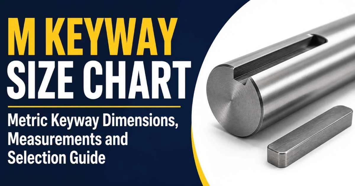
A metric keyway is a machined slot in a shaft, hub, or other mechanical component that accommodates a key to help transmit torque between connected parts. Keyways are widely used in motors, gearboxes, pumps, pulleys, sprockets, couplings, and industrial machinery.
Choosing the correct keyway size is essential for proper alignment, reliable torque transmission, and a secure mechanical connection. The key width, key height, slot depth, shaft diameter, and fit tolerances must be compatible with the applicable engineering standard.
This M keyway size chart guide explains common metric key dimensions, shaft diameter ranges, keyway measurements, standard terminology, and practical selection methods. It also covers how to measure an existing keyway, common machining mistakes, and the information to verify before manufacturing or replacing a key.
What Is a Metric Keyway?
A metric keyway is a slot machined into a component to accommodate a mechanical key. The key is typically a separate metal part positioned between a shaft and a mounted component, such as a gear, pulley, sprocket, or coupling.
In a conventional keyed connection, the key helps prevent relative rotation between the shaft and hub, allowing torque to pass from one component to the other.
A keyway may be machined into:
- A rotating shaft
- The bore of a pulley or sprocket
- A gear or coupling hub
- A pump or motor component
- Industrial transmission equipment
Metric keyways use millimeters for their nominal dimensions. For example, a 6 mm wide keyway is designed for a compatible key with a nominal width of 6 mm, subject to the applicable tolerances.
The exact dimensions depend on the keyway type, shaft diameter, engineering standard, and application.
Keyway vs. Key: What Is the Difference?
A key is the separate component that fits between mating parts. A keyway is the slot that receives that key.
For example, a parallel key may fit partly into a shaft keyway and partly into a matching hub keyway. The key transfers torque through contact with the sides of the slots.
A correctly designed connection requires compatible key dimensions and suitable shaft and hub geometry. Simply matching the key width does not guarantee that the assembly is correct.
Metric Keyway Size Chart: Standard Key Width and Height
Metric parallel keys are commonly selected according to shaft diameter and the applicable standard, such as DIN 6885 or another specified national or international standard.
The following table provides a general reference for common parallel-key dimensions. The listed dimensions are nominal key width × key height, in millimeters.
| Shaft Diameter Range (mm) | Key Width (mm) | Key Height (mm) | Typical Key Designation |
|---|---|---|---|
| 6–8 | 2 | 2 | 2 × 2 |
| Over 8–10 | 3 | 3 | 3 × 3 |
| Over 10–12 | 4 | 4 | 4 × 4 |
| Over 12–17 | 5 | 5 | 5 × 5 |
| Over 17–22 | 6 | 6 | 6 × 6 |
| Over 22–30 | 8 | 7 | 8 × 7 |
| Over 30–38 | 10 | 8 | 10 × 8 |
| Over 38–44 | 12 | 8 | 12 × 8 |
| Over 44–50 | 14 | 9 | 14 × 9 |
| Over 50–58 | 16 | 10 | 16 × 10 |
| Over 58–65 | 18 | 11 | 18 × 11 |
| Over 65–75 | 20 | 12 | 20 × 12 |
| Over 75–85 | 22 | 14 | 22 × 14 |
| Over 85–95 | 25 | 14 | 25 × 14 |
| Over 95–110 | 28 | 16 | 28 × 16 |
| Over 110–130 | 32 | 18 | 32 × 18 |
| Over 130–150 | 36 | 20 | 36 × 20 |
Important: This is a general selection reference for common parallel keys, not a substitute for the applicable standard’s complete dimensional tables. Verify the shaft diameter limits, key dimensions, keyway depths, corner radii, and tolerances against the standard and manufacturer’s drawing before machining.
How to Read a Metric Key Size
A key designation such as 8 × 7 mm normally identifies its nominal width and height:
- 8 mm: Key width.
- 7 mm: Key height.
- Key length: A separate dimension selected according to the hub length and torque requirements.
The designation does not specify every keyway dimension. The shaft-slot depth and hub-slot depth must also be established using the applicable standard.
Metric Keyway Dimensions: Width, Depth, and Length
A keyway drawing usually includes several dimensions. Each serves a different purpose in ensuring that the key fits correctly and transmits torque as intended.
| Dimension | Symbol or Description | Purpose |
|---|---|---|
| Key width | bb | Determines the nominal width of the key and matching slots |
| Key height | hh | Defines the vertical dimension of the key |
| Key length | LL | Determines how far the key extends along the shaft |
| Shaft keyway depth | t1t_1 | Specifies the depth of the slot machined into the shaft |
| Hub keyway depth | t2t_2 | Specifies the depth of the slot inside the hub |
| Shaft diameter | dd | Establishes the shaft size used for key selection |
| Corner radius | Application-specific | Affects the keyway geometry and compatibility |
| Width tolerance | Standard-specific | Controls the permitted variation in keyway width |
Keyway Width
Keyway width is the distance across the slot’s parallel sides. It must match the intended key width and the specified fit.
The fit may be designed to allow assembly, provide accurate positioning, or accommodate particular operating requirements. The correct tolerance depends on the standard and application.
Keyway Depth
Keyway depth describes how far the slot extends into the shaft or hub. These depths are not necessarily equal.
In a typical parallel-key connection, part of the key sits in the shaft slot while the remaining portion engages the hub slot. The dimensional relationship must follow the applicable design standard.
Do not assume that the shaft keyway depth is half the key height or that the hub slot depth is identical. Use the specified dimensions for the selected key size.
Key Length
Key length is selected according to the available shaft and hub geometry, along with the torque being transmitted.
A longer key provides a greater potential contact area along the shaft, but length alone does not establish the connection’s capacity. Key material, shaft material, hub material, loading, and the applicable design method must also be considered.
For a standard parallel key, the key should fit the intended working length without interfering with shoulders, radii, or other features.
Common Metric Keyway Sizes and Applications
Metric key sizes vary with shaft diameter and mechanical design. The following examples illustrate common selection situations rather than specifying a key for every component.
Small Keys: 2 × 2 mm to 5 × 5 mm
Small keys may be used in compact mechanisms and lighter-duty assemblies where the shaft diameter and loading permit their use.
Potential applications include:
- Small pulleys
- Compact drive mechanisms
- Instrument or equipment assemblies
- Selected small motor components
The suitability of a small key depends on the actual torque, shaft material, hub geometry, and engineering requirements.
Medium Keys: 6 × 6 mm to 12 × 8 mm
These dimensions occur in a range of general mechanical equipment.
Possible applications include:
- Gearbox components
- Couplings
- Pumps and motor drives
- Medium-sized pulleys and sprockets
- Industrial transmission assemblies
The correct key must match the shaft and hub keyways. Confirm the dimensions and tolerances rather than relying on the application name alone.
Larger Keys: 14 × 9 mm and Above
Larger keys may be specified for larger shafts and more substantial mechanical assemblies.
Potential applications include:
- Industrial machinery
- Large couplings
- Gear drives
- Heavy-duty pulley systems
- Specialized power transmission equipment
A larger key does not automatically make a connection suitable for heavy loads. The design must be checked for key shear, bearing pressure, shaft weakening, hub strength, and other relevant failure modes.
Types of Metric Keys and Keyways
Different key designs serve different mechanical purposes. A keyway size chart for one type of key should not automatically be applied to another.
Parallel Keys
Parallel keys have a generally rectangular cross-section with parallel sides. Their width and height remain nominally constant along the length.
They are commonly used in shafts and hubs for power transmission. Their dimensions and fits are specified by the relevant engineering standard.
Taper Keys
Taper keys have a tapered working surface or body, depending on the design. The taper helps create a wedging action during installation.
Their dimensions, taper, installation method, and fit requirements differ from those of ordinary parallel keys. A parallel-key dimension table should not be used as a complete specification for a taper key.
Woodruff Keys
Woodruff keys are semicircular or disc-shaped keys that fit into a curved seat machined into a shaft. They are used in certain machinery and automotive applications.
Their selection involves the key’s width, diameter, height, and corresponding seat geometry. Their dimensions cannot be established from a parallel-key chart alone.
Feather Keys
Feather keys are designed to transmit torque while permitting relative axial movement between compatible components in specified arrangements.
The design may use a key secured to one component or another configuration defined by the machinery. Axial movement, retention, and contact conditions must be considered during selection.
Special and Custom Keys
Some applications use keys with nonstandard dimensions, special materials, or customized geometry.
For replacement work, follow the original equipment drawing or obtain an approved engineering specification. Do not assume that a custom key can be replaced safely using the nearest standard size.
Also Read:
How to Measure an Existing Metric Keyway
If the original drawing is unavailable, measuring the existing shaft, key, and hub can help identify the required dimensions. However, worn or damaged components may not provide reliable reference dimensions.
Step 1: Measure the Shaft Diameter
Use an appropriate micrometer or caliper to measure the shaft diameter on an undamaged cylindrical surface.
Record the result in millimeters. If the shaft is worn, tapered, or out of round, take measurements at suitable positions and investigate any variation.
Use the nominal shaft diameter and the relevant standard to identify the expected key size.
Step 2: Measure the Key Width
Remove the key if it can be removed safely and measure its width across the parallel sides.
A micrometer or suitable caliper can help establish the dimension. Check for wear, burrs, deformation, and damage that may affect the measurement.
Do not rely exclusively on a worn key to determine the original nominal size.
Step 3: Measure the Key Height
Measure the vertical dimension of the key. If the key has rounded edges, a taper, or a nonstandard profile, compare its shape with the original specification.
Record the nominal height separately from the keyway depths.
Step 4: Measure the Shaft Slot Depth
The shaft keyway depth is measured from the original shaft surface to the bottom of the slot.
A depth-measuring instrument or suitable inspection method may be required, depending on the slot dimensions and accessibility.
Remove dirt and burrs before measuring. Damaged slot edges can interfere with accurate readings.
Step 5: Check the Hub Keyway
Inspect the hub’s internal slot and measure its width and depth where practical.
For internal features, access and instrument geometry can limit direct measurement. Use a drawing or appropriate inspection equipment when the dimensions cannot be measured reliably.
Step 6: Verify the Key Length and Fit
Measure the usable slot length and compare it with the key length and hub geometry.
The key should fit the intended assembly without unwanted interference. Confirm the specified width tolerance and the requirements for the shaft and hub before manufacturing a replacement.
Also Read:
How to Select the Correct Metric Keyway Size
Correct keyway selection requires a combination of dimensional matching and mechanical design considerations.
Identify the Shaft Diameter
Start with the nominal shaft diameter. Use the relevant standard’s size table to identify the corresponding key width and height.
If the shaft diameter falls near a size boundary, verify the exact range and inclusivity specified by the standard rather than rounding the measurement.
Confirm the Applicable Standard
DIN 6885 is a widely used reference for parallel keys and associated keyway dimensions. Other standards or equipment-specific drawings may apply.
Before machining, confirm the specified key type, nominal dimensions, slot depths, corner geometry, and tolerances.
Determine the Key Length
The required length depends on the hub length, shaft arrangement, transmitted torque, and design constraints.
Use the manufacturer’s engineering documentation or an appropriate mechanical design method to establish whether the selected key has sufficient capacity.
Check Material and Loading
Keyway design can affect the strength of the shaft and hub. Important considerations include:
- Transmitted torque
- Operating speed
- Shock or reversing loads
- Key and shaft materials
- Hub material and geometry
- Contact pressure and shear strength
- Fatigue and stress concentration
- Operating temperature and environment
For critical machinery, have the connection checked using an applicable engineering design method rather than choosing dimensions from a chart alone.
Verify the Finished Fit
After machining, inspect the slot width, depth, length, alignment, and surface condition.
The key should engage as specified without excessive clearance or unintended interference. Remove burrs carefully without changing the designed dimensions.
Also Read:
Common Keyway Machining Mistakes
Incorrect keyway dimensions can cause assembly problems, poor torque transmission, and premature component failure.
- Selecting a key by shaft diameter alone: Confirm the applicable standard and key type.
- Using the wrong slot width: A width mismatch can cause looseness or prevent assembly.
- Incorrect keyway depth: This changes the key’s engagement with the shaft and hub.
- Ignoring tolerances: Nominal dimensions alone do not define the required fit.
- Choosing an unsuitable key length: The connection may not provide the required capacity.
- Failing to deburr the slot: Burrs can interfere with assembly and accurate seating.
- Using a worn key as the only reference: Wear may distort the original dimensions.
- Ignoring shaft weakening: Keyways introduce geometric discontinuities that must be considered in the design.
- Mixing key standards: Dimensions and tolerances from different standards may not be interchangeable.
For a replacement keyway, the original drawing or applicable standard should take precedence over estimates based on appearance.
Metric Keyway Size Chart: Frequently Asked Questions
What does an 8 × 7 mm key size mean?
It normally means that the nominal key width is 8 mm and the nominal height is 7 mm. The key length is a separate dimension, and the corresponding shaft and hub keyway depths must be specified independently.
How do I determine the correct keyway size from shaft diameter?
Identify the nominal shaft diameter, then consult the relevant key standard or engineering drawing. Verify the key width, height, slot depths, and tolerances before manufacturing or ordering the key.
Are all metric keyways standardized?
No. Standardized dimensions exist for common key types, including parallel keys, but specialized machinery may use different standards or custom dimensions. Confirm the standard specified for the equipment.
What is the difference between keyway width and depth?
Width is measured across the slot’s sides, while depth is the distance from the original surface to the bottom of the slot. These dimensions serve different purposes and must be specified separately.
Can I use a parallel-key chart for a Woodruff key?
No. Woodruff keys have a different shape and require a matching curved seat. Use the appropriate dimensional chart and standard for the key type.
Why is keyway tolerance important?
Tolerance determines the permitted variation from a nominal dimension. It influences assembly, positioning, contact, and the performance of the keyed connection.
Does a larger key always transmit more torque?
Not necessarily. Torque capacity depends on key dimensions, material properties, engagement length, shaft and hub strength, loading conditions, and the applicable design criteria. A larger key must still be properly engineered for the assembly.
Conclusion
A metric keyway size chart provides a useful starting point for selecting parallel keys and matching shaft slots. The shaft diameter helps determine the nominal key width and height, but keyway depth, key length, tolerances, and mechanical loading must also be considered.
For reliable results, identify the applicable engineering standard, verify all dimensions against the manufacturer’s drawing, and inspect the finished fit before operating the machinery. Correct metric keyway selection supports dependable torque transmission and helps reduce the risk of looseness, excessive wear, and mechanical failure.