
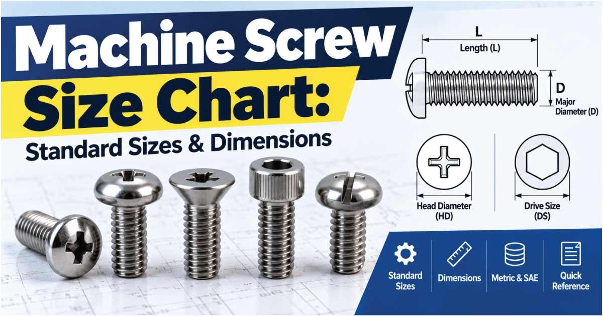
Choosing the right machine screw is easier when you know exactly what the size designation means. A machine screw must match the thread diameter, thread pitch or threads per inch, length, head style, drive type, and mating threaded hole. Using the wrong size can lead to poor engagement, damaged threads, loose joints, or assembly problems.
This machine screw size chart covers commonly used metric and SAE/inch machine screw sizes, including major diameter, thread pitch or threads per inch, and common designations. It also explains how machine screw sizes work, how to measure an existing screw, how metric and inch sizes differ, and how to select the correct screw for an application.
Metric machine screw threads are standardized under the ISO metric thread system. ISO 262:2023 specifies selected metric diameter-and-pitch combinations for commercial fasteners, while ISO 724 defines the basic dimensions of ISO general-purpose metric threads.
For inch-series machine screws, ASME B18.6.3 covers machine screws, tapping screws, and metallic drive screws, while thread dimensions for Unified National Coarse (UNC) and Unified National Fine (UNF) threads are defined through the Unified Thread Standard.
What Is a Machine Screw?
A machine screw is a threaded fastener designed primarily for installation into a pre-tapped threaded hole or threaded nut. Unlike many wood screws or self-tapping screws, a conventional machine screw normally does not create its own mating thread.
Machine screws are widely used in machinery, electrical equipment, appliances, electronics, automotive components, control panels, brackets, enclosures, and general mechanical assemblies.
They are available with different:
- Thread diameters
- Thread pitches
- Lengths
- Head styles
- Drive configurations
- Materials
- Finishes
- Strength and corrosion-resistance characteristics
The screw’s nominal size identifies its thread, but the complete specification may also include its length, head style, material, finish, and applicable standard.
For example, M6 × 1.0 × 30 mm describes a metric screw with a nominal 6 mm thread diameter, 1.0 mm pitch, and 30 mm nominal length.
An inch designation such as #10-32 × 1 in. identifies a No. 10 machine screw with 32 threads per inch and a nominal length of 1 inch.
Metric Machine Screw Size Chart
Metric machine screws use an M designation followed by the nominal outside or major diameter in millimeters. The thread pitch is normally specified in millimeters as the distance from one thread crest to the next.
The table below provides common metric machine screw thread sizes. Actual screw availability depends on the manufacturer, head style, material, and applicable product standard.
| Metric Size | Nominal Diameter (mm) | Common Coarse Pitch (mm) | Typical Use |
|---|---|---|---|
| M2 | 2.0 | 0.40 | Small electronics |
| M2.5 | 2.5 | 0.45 | Electronics and light assemblies |
| M3 | 3.0 | 0.50 | Electronics and machinery |
| M4 | 4.0 | 0.70 | General assemblies |
| M5 | 5.0 | 0.80 | Machinery and brackets |
| M6 | 6.0 | 1.00 | General mechanical work |
| M8 | 8.0 | 1.25 | Machinery and equipment |
| M10 | 10.0 | 1.50 | Larger mechanical assemblies |
| M12 | 12.0 | 1.75 | Heavy-duty assemblies |
These are nominal thread dimensions, not necessarily the exact measured diameter of a finished screw. Manufacturing tolerances mean an actual screw will not always measure exactly at its nominal diameter.
ISO 262:2023 covers selected metric screw-thread diameter and pitch combinations from 1 mm through 100 mm, making it a useful reference when determining standardized metric fastener sizes.
Metric Fine-Thread Sizes
Metric systems also include fine pitches. A designation such as M8 × 1.0 means the nominal diameter is 8 mm and the pitch is 1.0 mm.
A smaller pitch means the threads are closer together.
Fine-thread machine screws can be useful when:
- More precise adjustment is desirable.
- The available threaded section is relatively short.
- A finer thread engagement is required for a particular design.
- The application or manufacturer specifically calls for a fine pitch.
Do not assume that a screw with the same diameter will fit every M-size threaded hole. M8 × 1.25 and M8 × 1.0 are different threads and should not be interchanged.
SAE and Inch Machine Screw Size Chart
In the United States, many machine screws are identified using number sizes rather than metric M designations. Common smaller sizes include #0 through #12, followed by fractional-inch diameters such as 1/4 inch, 5/16 inch, and 3/8 inch.
Unified threads are commonly divided into UNC (Unified National Coarse) and UNF (Unified National Fine) series. UNC and UNF use the same nominal diameter for a given size but have different thread pitches.
| Size | Major Diameter (in) | Major Diameter (mm) | UNC (TPI) | UNF (TPI) |
|---|---|---|---|---|
| #0 | 0.0600 | 1.52 | — | 80 |
| #1 | 0.0730 | 1.85 | 64 | 72 |
| #2 | 0.0860 | 2.18 | 56 | 64 |
| #3 | 0.0990 | 2.51 | 48 | 56 |
| #4 | 0.1120 | 2.84 | 40 | 48 |
| #5 | 0.1250 | 3.18 | 40 | 44 |
| #6 | 0.1380 | 3.51 | 32 | 40 |
| #8 | 0.1640 | 4.17 | 32 | 36 |
| #10 | 0.1900 | 4.83 | 24 | 32 |
| #12 | 0.2160 | 5.49 | 24 | 28 |
| 1/4 in. | 0.2500 | 6.35 | 20 | 28 |
| 5/16 in. | 0.3125 | 7.94 | 18 | 24 |
| 3/8 in. | 0.3750 | 9.53 | 16 | 24 |
| 7/16 in. | 0.4375 | 11.11 | 14 | 20 |
| 1/2 in. | 0.5000 | 12.70 | 13 | 20 |
The major diameters and UNC/UNF thread counts above correspond to commonly published Unified thread dimensions.
For example, 1/4-20 UNC has a nominal diameter of 1/4 inch and 20 threads per inch, while 1/4-28 UNF has the same nominal diameter but 28 threads per inch.
How Machine Screw Sizes Are Designated
A machine screw designation normally contains several pieces of information.
Metric Designation
A typical metric designation is:
M6 × 1.0 × 30 mm
This means:
- M = metric thread
- 6 = nominal diameter of 6 mm
- 1.0 = thread pitch of 1.0 mm
- 30 mm = nominal screw length
Some metric product descriptions omit the pitch when the standard coarse pitch is assumed. However, for accurate identification, specifying the pitch is preferable whenever there is any possibility of confusion.
Inch Designation
An inch machine screw might be identified as:
#10-32 × 1 in.
Here:
- #10 = nominal screw size
- 32 = 32 threads per inch
- 1 in. = nominal screw length
A fractional designation works similarly:
1/4-20 × 1 in.
This identifies a 1/4-inch nominal diameter, 20-TPI thread, and 1-inch nominal length.
Machine Screw Dimensions You Need to Know
Thread diameter and length are important, but they are not the only dimensions that matter.
Major Diameter
The major diameter is the largest diameter of the external screw thread, measured approximately from crest to crest.
It is the primary dimension used to identify a metric M size or an inch screw’s nominal diameter.
For example:
- M6 has a nominal diameter of 6 mm.
- M8 has a nominal diameter of 8 mm.
- #10 has a nominal major diameter of approximately 0.190 inch.
- 1/4 inch has a nominal diameter of 0.250 inch.
The actual measured thread diameter can be slightly different because of manufacturing tolerances and thread geometry.
Thread Pitch
Metric thread pitch is measured in millimeters per thread.
For example, an M6 × 1.0 thread advances 1.0 mm for each complete revolution under ideal conditions.
A smaller metric pitch means more closely spaced threads.
Threads Per Inch
In inch systems, thread spacing is usually specified as TPI, or threads per inch.
For example:
- 1/4-20 = 20 TPI
- 1/4-28 = 28 TPI
- #10-24 = 24 TPI
- #10-32 = 32 TPI
The higher the TPI, the finer the thread.
Screw Length
Screw length is another critical dimension. For many conventional machine screws, length is measured from under the head to the tip.
Countersunk or flat-head screws are an important exception because the head is designed to sit flush with the surface. Therefore, the relevant overall dimension can be different from that of a pan-head or round-head screw.
Always check the applicable product standard or manufacturer’s dimensional drawing when length is critical.
Common Machine Screw Head Types
Machine screws are manufactured with several head styles. The correct head depends on clearance, appearance, installation method, and the surrounding component.
Pan Head
A pan head has a rounded top and relatively broad bearing surface. It is common in general-purpose mechanical and electrical applications.
Flat or Countersunk Head
A countersunk screw has a tapered underside designed to sit flush with a countersunk hole.
It is useful when a protruding head would interfere with another component.
Oval or Raised Countersunk Head
This style combines a countersunk underside with a slightly rounded top. It can provide a finished appearance while maintaining a relatively low profile.
Truss Head
A truss head has a broad, low-profile head that provides a larger bearing surface. It is useful where distributing clamping force over a wider area is desirable.
Socket Head
Socket-head machine screws use an internal hexagonal drive. They are often selected where external wrench clearance is limited.
The head style is separate from the thread size. For example, two M6 screws can have the same thread but completely different head and drive configurations.
Machine Screw Drive Types
The drive determines which tool is used to install or remove the screw.
Common drive types include:
- Phillips
- Slotted
- Pozidriv
- Hex socket
- Torx or hexalobular
- Combination drives
A screw’s drive size should not be confused with its thread size.
For example, an M5 Phillips machine screw describes an M5 thread, while the Phillips recess describes how the screw is driven. The exact recess dimensions depend on the applicable product standard and manufacturer.
ISO product standards cover particular combinations of metric machine screw head styles and drives. For example, ISO 7045 specifies pan-head screws with type H or type Z cross recesses in product grade A for threads from M1.6 through M10.
How to Measure a Machine Screw
If you have an unidentified machine screw, measuring it systematically is usually more reliable than guessing from appearance.
1. Measure the Thread Diameter
Use a digital caliper to measure across the threaded portion.
For metric screws, a result near 6 mm may indicate M6. For inch screws, a measurement near 0.190 inch may indicate #10.
Remember that the measured value does not need to be perfectly identical to the nominal size.
2. Determine the Thread Pitch
For a metric screw, use a metric thread pitch gauge or measure the distance between adjacent thread crests.
For an inch screw, use a TPI gauge or determine the number of threads over a measured one-inch distance.
3. Measure the Length
Measure the screw according to its head style.
For a conventional pan-head screw, measure from the underside of the head to the end of the threaded shank. For countersunk screws, check the relevant specification because the head geometry changes how length is referenced.
4. Identify the Head and Drive
Record whether the screw has:
- Pan head
- Flat/countersunk head
- Oval head
- Truss head
- Socket head
- Slotted drive
- Phillips drive
- Hex or Torx drive
5. Check the Material and Finish
If the application is important, identify the material and finish as well. Stainless steel, carbon steel, alloy steel, brass, and other materials have different properties and suitability.
Discover More:
Metric vs SAE Machine Screws
Metric and inch machine screws can look very similar, particularly when their diameters are close.
However, they should not be treated as interchangeable simply because their diameters appear similar.
| Feature | Metric | SAE/Inch |
|---|---|---|
| Diameter identification | M designation | Number or fractional inch |
| Thread spacing | Pitch in mm | Threads per inch |
| Common thread series | Metric coarse/fine | UNC/UNF |
| Example | M6 × 1.0 | #10-32 |
| Typical measurement tools | Metric caliper and pitch gauge | Inch caliper and TPI gauge |
| Thread standard | ISO metric system | Unified Thread Standard |
The important difference is thread geometry and pitch, not simply diameter.
For example, an M6 screw has a nominal diameter of 6 mm, while a 1/4-inch screw has a nominal diameter of 6.35 mm. Even though these dimensions are relatively close, their threads are not automatically compatible.
Never force an apparently similar screw into a threaded hole. If the pitch is wrong, forcing the screw can damage the internal thread.
How to Choose the Correct Machine Screw
Selecting the right machine screw involves more than matching diameter.
Match the Thread
First identify:
- Metric or inch thread
- Nominal diameter
- Pitch or TPI
- Coarse or fine thread
- Required thread engagement
The screw and mating hole must use compatible threads.
Choose the Correct Length
The screw should provide adequate thread engagement without bottoming out in a blind hole.
An excessively long screw can:
- Contact the bottom of a blind hole
- Interfere with internal components
- Protrude unnecessarily
- Prevent proper seating
An excessively short screw may provide insufficient engagement.
Select the Head Style
Choose a head based on the available space and desired installation.
For example:
- Use a countersunk head when a flush surface is required.
- Use a pan head for general-purpose fastening.
- Use a socket head when access is limited.
- Use a truss head when a broad bearing surface is useful.
Consider Material and Environment
The screw material should suit the environment.
For example, corrosion-resistant stainless steel may be appropriate for applications where corrosion resistance is important, while other materials may be selected for strength, cost, electrical properties, temperature resistance, or compatibility with mating components.
Discover More:
Common Machine Screw Mistakes
Several errors repeatedly cause problems during machine screw selection.
Mistaking Metric and Inch Threads
A screw may appear to fit because its diameter is close, but the pitch may be different.
Solution: Always identify the pitch or TPI before installation.
Ignoring Thread Length
A screw can have the correct diameter but still be unsuitable because it is too short or too long.
Solution: Measure the required engagement and available hole depth.
Confusing Head Size With Thread Size
The diameter of the screw head is not the same as the nominal thread diameter.
Solution: Identify the thread from the threaded shank, not the head.
Using the Wrong Drive Tool
A damaged recess can make removal difficult.
Solution: Match the driver to the specified drive type and size.
Forcing a Screw
If a machine screw becomes difficult to turn immediately, stop rather than applying excessive force.
Possible causes include:
- Wrong thread pitch
- Damaged threads
- Cross-threading
- Debris
- Incorrect screw size
- Bottoming in a blind hole
Machine Screw Applications
Machine screws are used across many industries because their standardized threads make them suitable for repeatable mechanical assembly.
Common applications include:
- Electrical enclosures
- Electronic equipment
- Appliances
- Machinery
- Automotive components
- Control panels
- Brackets and mounting plates
- Metal assemblies
- Industrial equipment
- Consumer products
- Small mechanical assemblies
Small number-size machine screws are especially common in compact equipment and electronics, while larger metric and fractional-inch sizes are used in machinery and structural equipment where the design calls for them.
The appropriate screw depends on the engineering requirements of the joint rather than the application name alone.
Discover More:
Machine Screw Size Chart: Quick Reference
The following condensed chart is useful when identifying common sizes.
| System | Common Size | Nominal Diameter | Common Thread |
|---|---|---|---|
| Metric | M2 | 2.0 mm | 0.40 mm pitch |
| Metric | M3 | 3.0 mm | 0.50 mm pitch |
| Metric | M4 | 4.0 mm | 0.70 mm pitch |
| Metric | M5 | 5.0 mm | 0.80 mm pitch |
| Metric | M6 | 6.0 mm | 1.00 mm pitch |
| Metric | M8 | 8.0 mm | 1.25 mm pitch |
| Metric | M10 | 10.0 mm | 1.50 mm pitch |
| Metric | M12 | 12.0 mm | 1.75 mm pitch |
| Inch | #4 | 0.112 in | 40/48 TPI |
| Inch | #6 | 0.138 in | 32/40 TPI |
| Inch | #8 | 0.164 in | 32/36 TPI |
| Inch | #10 | 0.190 in | 24/32 TPI |
| Inch | #12 | 0.216 in | 24/28 TPI |
| Inch | 1/4 in. | 0.250 in | 20/28 TPI |
| Inch | 5/16 in. | 0.3125 in | 18/24 TPI |
| Inch | 3/8 in. | 0.375 in | 16/24 TPI |
For exact production work, treat this as a reference rather than a substitute for the applicable engineering standard or manufacturer’s drawing. ASME’s B18 standards cover dimensional, physical, and performance requirements for various fastener products, including inch-series machine screws.
Frequently Asked Questions
What is the most common machine screw size?
There is no single universal most common size because machine screws are used across many industries. M3, M4, M5, and M6 are common metric sizes, while #6, #8, #10, and 1/4 inch are common in inch-based applications.
The correct size should always be determined by the threaded hole and engineering requirements.
What does M6 mean on a machine screw?
M6 indicates a metric screw with a nominal thread diameter of approximately 6 mm. It does not, by itself, fully specify the pitch, length, head style, material, or finish.
For example, M6 × 1.0 × 30 mm provides substantially more information.
What is the difference between #8-32 and #8-36?
Both are No. 8 screws with the same nominal major diameter, but they have different thread counts.
#8-32 has 32 threads per inch, while #8-36 has 36 threads per inch. They are therefore different thread pitches and should not be treated as interchangeable.
Is an M6 screw the same as a 1/4-inch screw?
No. Their nominal diameters are relatively close, but they use different thread systems. M6 is 6 mm nominal diameter, while 1/4 inch is 6.35 mm.
Thread pitch must also be compatible, so one should not be substituted for the other based only on diameter.
How do I know what size machine screw I have?
Measure the thread diameter, determine the pitch or TPI, measure the length, and identify the head and drive style.
A caliper and thread-pitch gauge are useful for reliable identification.
Can I use a machine screw in a wood or plastic hole?
A conventional machine screw is primarily designed to work with a compatible threaded hole or nut. It may be used with threaded inserts or other purpose-designed components in wood or plastic, but it should not automatically be treated as a wood screw or self-tapping screw.
Does screw length include the head?
For many conventional machine screws, length is measured from beneath the head to the tip. Countersunk screws are a notable exception because their head is designed to sit within the material.
Always verify the manufacturer’s measurement convention when ordering a critical fastener.
Final Takeaway
A reliable machine screw size chart helps you quickly identify common metric and SAE/inch thread sizes, but selecting the correct fastener requires more than matching diameter. You also need to confirm thread pitch or TPI, screw length, head style, drive type, material, and application requirements.
For metric screws, look for the M designation and pitch, such as M6 × 1.0. For inch screws, identify the number or fractional diameter together with the thread count, such as #10-32 or 1/4-20 UNC.
When an existing screw must be replaced, measure it rather than relying on appearance. If the application is safety-critical or the dimensions are tightly controlled, verify the complete specification against the applicable standard and manufacturer documentation before installation.