
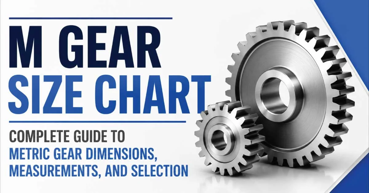
Gears are essential mechanical components used to transmit power, control speed, and change the direction of motion in machines. The metric gear sizing system, commonly represented by “M” or module size, is widely used in mechanical engineering and manufacturing. Selecting the correct M gear size is important because gear compatibility depends on module, tooth count, pitch diameter, pressure angle, and application requirements.
An M gear size chart helps engineers, designers, and technicians identify the correct gear dimensions for different mechanical systems. This complete guide explains metric gear sizes, module measurements, gear types, formulas, materials, and how to select the right gear for your application.
What Is an M Gear?
An M gear is a gear designed using the metric module system. Unlike inch-based gears that use diametral pitch, metric gears use module measurements to define tooth size.
The module is calculated by dividing the pitch diameter by the number of teeth. A higher module creates larger teeth, allowing the gear to handle higher loads.
Metric gears are commonly used in:
- Industrial machines
- Robotics systems
- Automotive transmissions
- Manufacturing equipment
- Gearboxes
- Automation systems
- Mechanical tools
M Gear Size Chart (Metric Gear Chart)
The “M” value in gear specifications refers to the module. The module represents the relationship between the gear pitch diameter and the number of teeth. A larger module indicates larger and stronger gear teeth.
| Module (M) | Tooth Size | Common Pitch Diameter Range | Applications |
|---|---|---|---|
| M0.5 | Very Small Teeth | 5 – 50 mm | Small instruments, electronics |
| M1 | Small Teeth | 10 – 100 mm | Precision machinery |
| M1.5 | Medium Small Teeth | 20 – 150 mm | Automation equipment |
| M2 | Medium Teeth | 30 – 250 mm | General machinery |
| M3 | Large Teeth | 50 – 400 mm | Industrial equipment |
| M4 | Heavy Teeth | 100 – 500 mm | Heavy machinery |
| M5 and above | Extra Heavy Teeth | 200 mm+ | Large industrial systems |
The exact dimensions depend on tooth count, gear type, pressure angle, and manufacturer specifications.
Understanding Gear Module Size
The module is the most important measurement when selecting compatible gears. Two gears must have the same module to properly mesh together.
For example:
- An M2 gear can only properly work with another M2 gear.
- An M3 gear requires another M3 gear with matching specifications.
The module affects:
- Tooth size
- Gear strength
- Overall gear diameter
- Load capacity
- Machine performance
Larger modules are generally used for applications requiring greater torque and durability.
Metric Spur Gear Size Chart
Spur gears are the most common type of gear. They have straight teeth and are used to transmit power between parallel shafts.
| Module Size | Common Tooth Range | Typical Applications |
|---|---|---|
| M0.5 | 10 – 100 teeth | Small mechanisms |
| M1 | 12 – 150 teeth | Precision devices |
| M2 | 15 – 200 teeth | Industrial machines |
| M3 | 20 – 250 teeth | Heavy machinery |
| M4 | 25 – 300 teeth | High-load systems |
Spur gears are popular because they are simple, efficient, and easy to manufacture.
Metric Bevel Gear Size Chart
Bevel gears are used to transfer motion between shafts that intersect at an angle, commonly 90 degrees.
| Module Size | Common Uses |
|---|---|
| M1 | Small angle transmission systems |
| M2 | Industrial equipment |
| M3 | Automotive and machinery |
| M4+ | Heavy-duty applications |
Bevel gears are selected based on module, tooth count, shaft angle, and operating load.
Metric Worm Gear Size Chart
Worm gears provide high reduction ratios and are commonly used where compact designs and controlled movement are required.
| Module Size | Application |
|---|---|
| M1 | Small control systems |
| M2 | Automation equipment |
| M3 | Industrial drives |
| M4 and above | Heavy machinery |
Worm gears are often used in conveyors, lifts, steering systems, and positioning equipment.
Also Read: Chainsaw Chain Size Guide: How to Choose the Right Chain
How to Measure an M Gear Size
Accurate measurements are required when replacing or designing gears. Important gear dimensions include module, tooth count, pitch diameter, and outside diameter.
Measure Gear Tooth Count
The number of teeth directly affects the gear ratio and overall size. Count every tooth around the gear circumference.
Measure Pitch Diameter
Pitch diameter is the imaginary circle where two gears effectively contact each other during operation.
The pitch diameter is related to the module and tooth count.
Measure Outside Diameter
The outside diameter is the total diameter measured across the gear teeth. It helps determine the physical size of the gear.
Check Pressure Angle
Pressure angle affects how gears transfer force. Common metric gear pressure angles include:
- 20 degrees
- 14.5 degrees
- 25 degrees
Gears must have matching pressure angles to operate correctly.
Common Metric Gear Materials
The material of a gear determines its strength, durability, and operating performance.
Steel Gears
Steel gears are widely used for high-strength applications where heavy loads and long service life are required.
Advantages include:
- High load capacity
- Excellent wear resistance
- Long operating life
Steel gears are common in industrial machinery, automotive systems, and gearboxes.
Plastic Gears
Plastic gears are lightweight and suitable for low-load applications where quiet operation is important.
Benefits include:
- Low noise operation
- Corrosion resistance
- Lightweight design
- Lower manufacturing cost
Plastic gears are often used in electronics, appliances, and small mechanisms.
Brass Gears
Brass gears provide good corrosion resistance and smooth operation. They are commonly used in precision equipment and moderate-load applications.
Also Read: Jigsaw Blade Size: Complete Guide 2026 + Pdf
Metric Gear Standards
Metric gears are manufactured according to international standards to ensure compatibility and performance.
Common standards include:
- ISO gear standards
- DIN gear specifications
- AGMA gear guidelines
Standardization helps manufacturers produce gears with consistent dimensions.
When selecting an M gear, consider:
- Module size
- Number of teeth
- Pressure angle
- Gear diameter
- Material type
- Operating speed
- Load requirements
Common M Gear Problems
Incorrect gear selection or poor maintenance can cause several mechanical issues.
Gear Tooth Wear: Continuous operation under heavy loads can wear down gear teeth and reduce efficiency.
Incorrect Gear Mesh: Gears with different modules or pressure angles may not operate correctly and can cause excessive noise.
Gear Breakage: Overloading or using an undersized gear can result in tooth failure.
Excessive Noise and Vibration: Poor alignment, incorrect spacing, or damaged teeth can create unwanted vibration during operation.
How to Choose the Right M Gear Size
Selecting the correct metric gear requires understanding the machine requirements and operating conditions.
Consider these factors:
- Required torque
- Gear ratio
- Operating speed
- Available space
- Module size
- Number of teeth
- Shaft arrangement
- Environmental conditions
For small precision devices, lower module gears are usually suitable. Heavy industrial applications require larger modules with stronger materials.
Also Read: Rivet Size Guide: How to Choose the Right Rivet
Final Thoughts on M Gear Sizes
An M gear size chart provides an essential reference for selecting the correct metric gear for mechanical applications. Understanding module size, tooth count, pitch diameter, and material options helps ensure proper gear performance.
Whether used in robotics, automotive systems, industrial machines, or manufacturing equipment, choosing the correct M gear size improves efficiency, reliability, and service life. Always verify gear specifications and compatibility before installation to achieve smooth and dependable operation.