
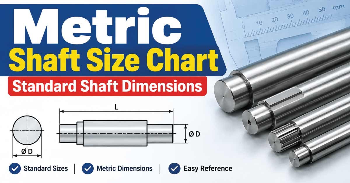
Choosing the correct shaft diameter is important for machine performance, bearing fit, power transmission, and component alignment. A shaft that is too small may not provide enough strength, while an incorrectly sized shaft can create problems with bearings, couplings, gears, pulleys, or seals.
A metric shaft size chart provides a quick reference for common shaft diameters used in mechanical equipment and machinery. However, shaft selection involves more than simply choosing the nearest diameter. The required size depends on load, torque, speed, material, length, support conditions, keyways, fits, and dimensional tolerances.
This guide explains standard metric shaft sizes, shaft dimensions, measurement methods, shaft tolerances, bearing fits, keyways, and practical selection factors. The charts are intended as general engineering references; exact dimensions should always be checked against the applicable drawing, manufacturer specification, or engineering standard.
Metric Shaft Size Chart
Metric shafts are commonly specified by their nominal diameter in millimeters (mm). The following chart provides a practical reference for commonly encountered metric shaft diameters.
| Nominal Shaft Diameter (mm) | Diameter (in) | Typical General Applications |
|---|---|---|
| 5 | 0.197 | Small mechanisms, instruments |
| 6 | 0.236 | Small machinery and assemblies |
| 8 | 0.315 | Small motors and mechanisms |
| 10 | 0.394 | Light machinery |
| 12 | 0.472 | Motors, rollers, mechanisms |
| 15 | 0.591 | General machinery |
| 16 | 0.630 | Bearings and machine components |
| 20 | 0.787 | Shafts, rollers, drives |
| 25 | 0.984 | Motors, gear drives, machinery |
| 30 | 1.181 | Industrial machinery |
| 35 | 1.378 | Drive and transmission components |
| 40 | 1.575 | Heavy machinery |
| 45 | 1.772 | Industrial drives |
| 50 | 1.969 | Large rotating equipment |
| 55 | 2.165 | Industrial shafts |
| 60 | 2.362 | Heavy-duty machinery |
| 65 | 2.559 | Drive systems |
| 70 | 2.756 | Large mechanical equipment |
| 75 | 2.953 | Heavy industrial applications |
| 80 | 3.150 | Large shafts and drives |
| 90 | 3.543 | Heavy machinery |
| 100 | 3.937 | Large industrial equipment |
The values above represent nominal shaft diameters, not necessarily the actual measured diameter of a finished shaft. A manufactured shaft may have a specified tolerance that determines the allowable deviation from its nominal dimension.
What Is a Metric Shaft?
A metric shaft is a cylindrical mechanical component whose principal dimensions are specified using the metric system, normally in millimeters. Shafts are used to transmit torque, support rotating components, maintain alignment, or provide a mounting surface for bearings and other machine elements.
A typical shaft may include several different diameter sections rather than having one constant diameter.
For example, a stepped shaft could have:
- A 20 mm bearing seat
- A 25 mm gear mounting section
- A 30 mm shoulder
- A smaller threaded end
- A keyway for torque transmission
This means that the phrase shaft size can refer to the nominal diameter of a particular section rather than the overall dimensions of the complete shaft.
Nominal Diameter vs Actual Diameter
The nominal diameter is the reference dimension used to identify the shaft. The actual manufactured diameter can be slightly larger or smaller depending on the specified tolerance.
For example, a shaft identified as 25 mm should not automatically be assumed to measure exactly 25.000 mm at every location. If the shaft is intended for a precision bearing fit, its allowable dimensional variation may be tightly controlled.
Common Metric Shaft Diameters
Metric shaft sizes are available across a very broad range. Small diameters are common in compact mechanisms, while larger diameters are used for industrial power transmission and heavy equipment.
Small Metric Shafts
Shafts from approximately 5 mm to 16 mm are frequently found in compact machinery and mechanisms.
Typical applications include:
- Small motors
- Robotics
- Instrument mechanisms
- Rollers
- Fans
- Small gear systems
- Hobby and laboratory equipment
The smaller the shaft, the more important it becomes to consider bending, deflection, surface damage, and manufacturing tolerances.
Medium Metric Shafts
Diameters from roughly 20 mm to 50 mm are common in general mechanical equipment.
They may be used for:
- Electric motors
- Gearboxes
- Pumps
- Conveyor systems
- Machine tools
- Rollers
- Couplings
- Agricultural equipment
These shaft sizes provide a practical range for many general-purpose applications, but the appropriate diameter still depends on the actual load and operating conditions.
Large Metric Shafts
Shafts above approximately 50 mm are generally associated with larger industrial machinery and higher loads, although application requirements vary considerably.
Examples include:
- Industrial drive systems
- Heavy conveyors
- Large gearboxes
- Crushers
- Processing machinery
- Large pumps
- Power transmission equipment
Large shafts require careful consideration of machining, alignment, material strength, keyways, stress concentrations, and support bearings.
Metric Shaft Dimensions and What to Measure
A shaft’s diameter is only one part of its complete dimensional specification. When replacing or designing a shaft, several dimensions may need to be measured.
Important Shaft Dimensions
Common shaft dimensions include:
- Outside diameter
- Overall shaft length
- Individual stepped diameters
- Shoulder locations
- Keyway width and depth
- Thread diameter and length
- Bearing-seat length
- Groove dimensions
- Fillet or shoulder radius
- Center-to-center distances
- Runout or concentricity requirements
A replacement shaft should match the functional dimensions, not simply the largest diameter visible on the component.
Shaft Diameter
Diameter is usually the first measurement taken. It directly affects compatibility with bearings, couplings, gears, pulleys, and other components.
For a precision application, measure the shaft at several locations rather than relying on a single measurement. Wear, corrosion, machining errors, or damage can cause the diameter to vary.
How to Measure a Metric Shaft
Measuring a shaft correctly is important when identifying an unknown component or ordering a replacement.
Using a Micrometer
For precision shaft diameters, an outside micrometer is generally preferable to a basic ruler or tape measure.
To measure:
- Clean the shaft surface.
- Remove dirt, grease, and burrs.
- Place the micrometer around the shaft.
- Apply the correct measuring force.
- Record the diameter.
- Repeat at different positions if accuracy is important.
Measure in more than one rotational orientation when checking for out-of-round conditions.
Using Vernier or Digital Calipers
Calipers are convenient for general measurements and larger dimensions. They are useful when high precision is not required, although a micrometer may provide better accuracy for critical shaft fits.
When measuring a worn shaft, do not assume the smallest or largest reading represents the original design diameter. Examine unworn sections or consult the original drawing or component specification.
Metric Shaft Tolerances and Fits
A nominal shaft diameter does not tell the entire story. Tolerance and fit determine how the shaft interacts with another component, such as a bearing or bushing.
A shaft may require a loose clearance fit, a transition fit, or an interference fit depending on how the assembly operates.
Why Shaft Tolerance Matters
Tolerance controls how much a manufactured shaft can deviate from its nominal dimension.
For example, a shaft intended to fit into a bearing cannot simply be machined to an arbitrary diameter close to the nominal value. The shaft and bearing dimensions must work together to produce the required fit.
Factors affecting the appropriate tolerance include:
- Rotational speed
- Applied load
- Bearing type
- Temperature
- Shaft material
- Housing material
- Assembly method
- Required positioning accuracy
Shaft and Bearing Fits
Bearings often have specific shaft-seat requirements. The correct fit depends partly on whether the bearing ring experiences a rotating or stationary load relative to the applied load.
For precision applications, use the bearing manufacturer’s shaft and housing recommendations rather than selecting a fit solely from a general chart.
Metric Shaft Size and Bearing Compatibility
One of the most common reasons for checking a metric shaft diameter is to identify a compatible bearing.
For example, a shaft with a 20 mm bearing seat requires a bearing with the appropriate 20 mm bore, subject to the required fit and dimensional tolerances.
| Shaft Diameter (mm) | Example Matching Bearing Bore (mm) | Important Consideration |
|---|---|---|
| 10 | 10 | Confirm bearing series and fit |
| 12 | 12 | Check shaft tolerance |
| 15 | 15 | Verify bearing specification |
| 17 | 17 | Common bearing bore size |
| 20 | 20 | Check load and fit requirements |
| 25 | 25 | Confirm shaft-seat tolerance |
| 30 | 30 | Verify bearing manufacturer’s limits |
| 35 | 35 | Check rotating-load conditions |
| 40 | 40 | Confirm fit and seat length |
| 45 | 45 | Check application requirements |
| 50 | 50 | Verify bearing and shaft tolerances |
A matching nominal bore does not automatically mean that the assembly is correctly designed. Bearing internal clearance, shaft tolerance, housing fit, operating temperature, and loading conditions can all influence the final result.
Discover More:
Metric Shaft Diameter Conversion to Inches
Metric shaft dimensions can be converted to inches using:
1 inch = 25.4 mm
Therefore:
Inches = millimeters ÷ 25.4
The following table provides common conversions.
| Metric Diameter (mm) | Approx. Diameter (in) | Approx. Fractional Inch Equivalent |
|---|---|---|
| 6 | 0.2362 | 15/64 |
| 8 | 0.3150 | 5/16 |
| 10 | 0.3937 | 25/64 |
| 12 | 0.4724 | 15/32 |
| 16 | 0.6299 | 5/8 |
| 20 | 0.7874 | 25/32 |
| 25 | 0.9843 | 63/64 |
| 30 | 1.1811 | 1-3/16 |
| 40 | 1.5748 | 1-37/64 |
| 50 | 1.9685 | 1-31/32 |
| 60 | 2.3622 | 2-23/64 |
| 75 | 2.9528 | 2-61/64 |
| 100 | 3.9370 | 3-15/16 |
These inch values are mathematical conversions, not necessarily standard inch shaft sizes. When replacing an existing shaft, do not substitute a nearby inch dimension merely because it appears close.
Standard Metric Shaft Sizes vs Custom Shaft Sizes
Standard shaft diameters are convenient because bearings, couplings, gears, and other components are often readily available for common dimensions.
However, machinery may require a custom diameter or a shaft with several special features.
Advantages of Standard Sizes
Using a standard metric shaft diameter can provide:
- Easier component sourcing
- Better compatibility with standard bearings
- Simplified manufacturing
- Lower machining complexity
- Easier maintenance
- More straightforward replacement
When a Custom Shaft May Be Necessary
A custom shaft can be appropriate when:
- The required load cannot be supported by a convenient standard diameter.
- Existing equipment uses a nonstandard dimension.
- Special mounting geometry is required.
- Multiple stepped sections are necessary.
- A particular keyway or thread arrangement is required.
- Space limitations prevent using the next standard diameter.
The important point is to design around the functional requirements, not simply the availability of a particular shaft size.
Discover More:
How to Choose the Correct Metric Shaft Size
Selecting a shaft diameter requires more than matching a component’s outside dimensions.
1. Determine the Load
Identify the radial, axial, and torsional loads acting on the shaft.
A shaft carrying significant torque may require a larger diameter than a shaft supporting only a light rotating component.
2. Calculate or Check Torque
For rotating power transmission, torque is a major consideration. Shaft diameter influences torsional stress, while shaft length and support arrangement influence bending and deflection.
For critical machinery, shaft sizing should be verified using appropriate engineering calculations.
3. Consider Shaft Length
Two shafts with the same diameter can behave differently if their unsupported lengths are different. A longer shaft can experience greater bending and deflection.
4. Account for Stress Concentrations
Keyways, grooves, shoulders, snap-ring grooves, holes, and abrupt diameter changes can create localized stress concentrations.
A shaft that looks sufficiently large based only on its nominal diameter may require additional analysis when these features are present.
5. Check Component Compatibility
Before selecting a diameter, check the bore or mounting dimension of:
- Bearings
- Gears
- Couplings
- Pulleys
- Sprockets
- Bushings
- Seals
6. Specify the Required Tolerance
A general-purpose shaft and a precision bearing shaft may have very different dimensional requirements even if both have the same nominal diameter.
Shaft Keyways and Their Effect on Dimensions
A keyway is a machined slot in a shaft used with a key to transmit torque between the shaft and a mounted component.
Keyways are common in:
- Gear shafts
- Motor shafts
- Pump shafts
- Conveyor drives
- Coupled machinery
A keyway changes the local cross-section of the shaft and therefore can affect its strength.
When specifying a shaft with a keyway, the shaft drawing should identify the relevant keyway width, depth, length, and location according to the applicable standard or engineering design.
Do not assume that every 25 mm shaft uses the same keyway dimensions. The appropriate key and keyway depend on the applicable standard and design requirements.
Discover More:
Metric Shaft Materials
Shaft dimensions cannot be separated from material selection. Two shafts with identical diameters can have significantly different performance characteristics because of differences in material, heat treatment, surface condition, and manufacturing process.
Common shaft materials include various grades of:
- Carbon steel
- Alloy steel
- Stainless steel
- Tool steel
- Specialty engineering materials
Material selection depends on the application.
For example, corrosion resistance may be important in wet or chemically aggressive environments, while high strength or fatigue resistance may be more important in heavily loaded rotating equipment.
Metric Shaft Surface Finish
The surface finish of a shaft can be particularly important at bearing seats, seal locations, and precision sliding interfaces.
A shaft does not necessarily need the same surface finish along its entire length.
Critical surfaces may require controlled machining processes such as:
- Turning
- Grinding
- Polishing
- Precision finishing
The required surface finish should be specified according to the mating component and application. For seals and precision bearing seats, follow the relevant component manufacturer’s requirements.
Common Metric Shaft Problems
Incorrect shaft dimensions or poor installation can contribute to mechanical problems.
Oversized Shaft
An oversized shaft may fail to fit into its intended bearing, bushing, coupling, or gear bore.
Forcing the component onto the shaft can damage the mating surfaces.
Undersized Shaft
An undersized shaft may produce excessive clearance. This can cause movement, vibration, wear, or poor alignment.
If the shaft has been worn below its intended size, replacing the shaft or using an approved repair method may be necessary.
Bent Shaft
A shaft can become bent because of excessive loads, impact, improper handling, or operating conditions.
A bent shaft can cause:
- Vibration
- Bearing wear
- Seal problems
- Coupling misalignment
- Uneven loading
Worn Bearing Seat
A bearing seat can wear over time, particularly when the fit is incorrect or the assembly experiences movement between mating surfaces.
Measure the seat carefully before ordering a replacement bearing or shaft.
Metric Shaft Size Selection Mistakes to Avoid
Several common mistakes can lead to incorrect shaft selection.
Choosing by diameter alone: Torque, bending, length, and loading also matter.
Ignoring tolerance: A nominal 25 mm dimension does not define the complete fit.
Using a nearby inch size: A similar-looking imperial dimension may not provide the required fit.
Measuring only one location: Wear or damage can cause diameter variation.
Ignoring keyways: Removing material from a shaft can affect its strength.
Forgetting shoulders: Bearing and seal positions may depend on shoulder geometry.
Skipping manufacturer specifications: Bearings, seals, and other components often have precise mounting requirements.
Assuming every shaft is interchangeable: Material, hardness, finish, and geometry can differ even when nominal diameter is identical.
Metric Shaft Dimensions for Replacement Parts
When replacing an existing shaft, create a complete dimensional record before ordering or machining the replacement.
Record:
- Overall length
- Every shaft diameter
- Length of each diameter section
- Bearing-seat dimensions
- Shoulder locations
- Keyway dimensions
- Thread sizes
- Threaded lengths
- Grooves and retaining features
- Surface condition
- Material or grade, when known
- Any specified tolerances
Photographs can help identify features, but accurate measurements and the original engineering drawing are more reliable for manufacturing.
If the shaft is part of safety-critical or heavily loaded equipment, the replacement should be verified by a qualified engineer rather than copied solely from a worn component.
Frequently Asked Questions About Metric Shaft Sizes
What are the most common metric shaft sizes?
Common sizes include 10, 12, 15, 16, 20, 25, 30, 35, 40, 45, 50, 60, 70, 75, and 80 mm, although many other diameters are available. The appropriate size depends on the machinery and design requirements.
Is a 25 mm shaft exactly 25 mm?
Not necessarily. 25 mm is the nominal diameter. The actual finished diameter depends on the specified tolerance, machining process, surface finish, and application.
How do I measure a metric shaft diameter?
Use a micrometer for precision measurements or calipers for general-purpose measurements. Clean the shaft first and measure several locations if wear, taper, or out-of-roundness may be present.
What metric shaft size fits a 20 mm bearing?
A bearing with a 20 mm bore is designed around a nominal 20 mm shaft, but the correct shaft tolerance and fit must be selected according to the bearing type, load, rotation, and manufacturer’s specifications.
Can I replace a metric shaft with an inch shaft?
Only when the dimensional and functional requirements are properly verified. A nearby inch diameter may not provide the correct bearing, coupling, seal, or interference fit.
Does shaft diameter determine strength?
Diameter has a major influence on shaft strength, but it is not the only factor. Material, shaft length, torque, bending load, keyways, shoulders, surface condition, and fatigue requirements can all affect performance.
What is the difference between shaft diameter and shaft length?
Shaft diameter describes the circular cross-sectional size, while shaft length describes the distance along the shaft. A complete shaft specification may contain several diameters and multiple lengths.
Final Takeaway
A metric shaft size chart is a useful starting point for identifying standard shaft diameters, comparing dimensions, and planning replacements. Common metric diameters range from small sizes used in compact mechanisms to much larger dimensions used in industrial machinery.
However, selecting a shaft should never depend on diameter alone. Load, torque, bending, length, material, tolerances, bearing fit, keyways, surface finish, and component compatibility all need to be considered.
For a replacement shaft, measure every functional dimension and compare the results with the original drawing or manufacturer’s specifications. For new or highly loaded machinery, use appropriate engineering calculations and applicable standards to verify that the selected shaft provides adequate strength, stiffness, fatigue resistance, and fit