
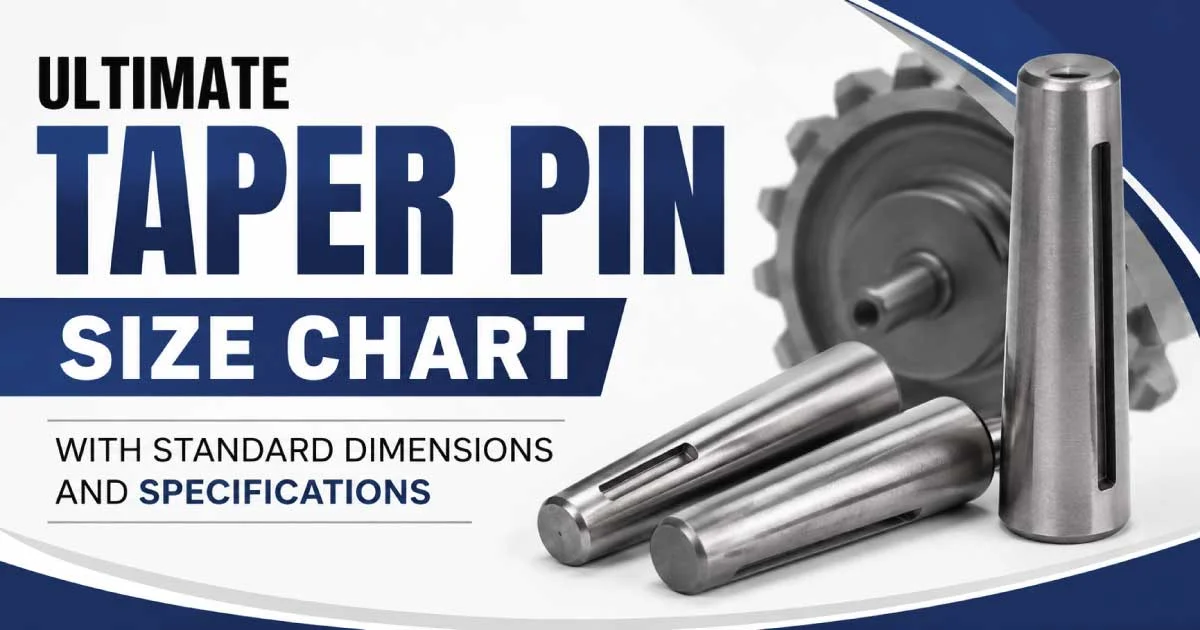
A taper pin is a precision fastener used to locate, align, and secure machine components. Its gradually tapered shape creates a close fit inside a matching tapered hole, helping maintain accurate positioning in mechanical assemblies. Choosing the correct size is essential for reliable alignment, repeatable assembly, and straightforward removal during maintenance.
This taper pin size chart explains standard dimensions, taper ratios, diameter measurements, length specifications, and common applications. It also covers how to measure an existing pin, select the correct replacement, and understand the differences between metric and inch-based standards.
Because taper pins are manufactured under different standards, the exact dimensions depend on the pin type and specification. Always verify critical measurements against the applicable standard or manufacturer’s dimensional drawing before machining a hole or ordering replacement hardware.
What Is a Taper Pin?
A taper pin is a solid cylindrical pin with a small, consistent reduction in diameter along its length. It fits into a correspondingly tapered hole, where the increasing interference as the pin enters helps secure the connected parts.
Unlike a straight dowel pin, which typically relies on a close cylindrical fit, a taper pin can be driven into position and seated firmly. This makes it useful for locating components that must return to a consistent position after disassembly.
How Does a Taper Pin Work?
A taper pin works through the interaction between its tapered surface and the matching hole. As the pin is inserted, its larger portion progressively engages the hole, creating a secure fit.
Common functions include:
- Positioning: Maintaining the relative position of two machine components.
- Alignment: Keeping shafts, levers, brackets, and housings correctly aligned.
- Retention: Preventing connected parts from shifting during normal operation.
- Repeatable assembly: Helping components return to their original position after servicing.
The pin must match the hole’s taper and dimensional requirements. A pin that is too large, too small, or manufactured to a different taper specification may not seat correctly.
Main Dimensions of a Taper Pin
Several measurements determine whether a taper pin will fit properly.
- Large-end diameter: The diameter measured at the larger end of the pin.
- Small-end diameter: The diameter measured at the narrower end.
- Length: The specified axial length of the pin.
- Taper ratio: The change in diameter relative to the pin’s length.
- Material and hardness: Properties that affect strength, wear resistance, and suitability for the application.
These dimensions should be considered together rather than selecting a pin based only on its largest diameter.
Metric Taper Pin Size Chart: Standard Dimensions
Metric taper pins are commonly specified according to ISO 2339, which covers unhardened metric taper pins. The standard includes nominal diameters from 0.6 mm through 50 mm, with dimensional tolerances and other requirements defined by the specification.
The following chart summarizes selected metric sizes and their approximate standard length ranges. Availability can vary by supplier, material, and manufacturing type.
| Nominal diameter (mm) | Approx. diameter change (mm) | Reference length range (mm) |
|---|---|---|
| 0.6 | 0.08 | 4–8 |
| 0.8 | 0.10 | 5–12 |
| 1.0 | 0.12 | 6–16 |
| 1.2 | 0.16 | 6–20 |
| 1.5 | 0.20 | 8–25 |
| 2.0 | 0.25 | 10–35 |
| 2.5 | 0.30 | 10–35 |
| 3.0 | 0.40 | 12–55 |
| 4.0 | 0.50 | 14–55 |
| 5.0 | 0.63 | 20–60 |
| 6.0 | 0.80 | 25–90 |
| 8.0 | 1.00 | 25–130 |
| 10.0 | 1.20 | 30–160 |
| 12.0 | 1.60 | 35–180 |
| 16.0 | 2.00 | 40–200 |
| 20.0 | 2.50 | 45–200 |
| 25.0 | 3.00 | 50–200 |
| 30.0 | 4.00 | 60–200 |
| 40.0 | 5.00 | 80–200 |
| 50.0 | 6.30 | 100–200 |
Source: ISO 2339 reference dimensions reproduced by RoyMech. The diameter-change figures are approximate reference values, not substitutes for dimensional tolerances or a manufacturer’s drawing.
How to Read the Metric Taper Pin Chart
The nominal diameter identifies the standardized pin size. It should not automatically be interpreted as the diameter at the narrow end or as the diameter at every point along the pin.
The diameter-change column illustrates how much the diameter changes over the pin’s specified length for the standard taper. The length range indicates reference availability, not a guarantee that every diameter is stocked in every listed length.
For example, a 6 mm nominal metric taper pin is a common size to investigate when replacing a small machine locating pin. However, you must still verify the original pin’s standard, length, fit, and material before ordering.
Important Notes About Metric Dimensions
- Metric taper pins under ISO 2339 use a 1:50 taper on diameter.
- Nominal diameters and dimensional tolerances must be interpreted according to the relevant standard.
- Turned and ground pins may have different manufacturing and surface-finish characteristics.
- The required length depends on the assembly and the amount of engagement needed.
- Do not use the chart alone to determine a precision hole’s final diameter.
Understanding Taper Pin Taper Ratio and Angle
The taper ratio describes how quickly a pin’s diameter changes along its length. It is one of the most important specifications because the pin and its mating hole must have compatible tapers.
What Does a 1:50 Taper Mean?
A 1:50 taper on diameter means the diameter changes by 1 unit for every 50 units of axial length.
The relationship is:
Taper ratio=D−dL\text{Taper ratio}=\frac{D-d}{L}Taper ratio=LD−d
Where:
- DDD = diameter at the larger end
- ddd = diameter at the smaller end
- LLL = axial length between the measurement points
For a metric pin with a 1:50 taper, the diameter difference is calculated as:
D−d=L50D-d=\frac{L}{50}D−d=50L
For example, over an axial distance of 50 mm, the diameter difference is 1 mm. Over 100 mm, it is 2 mm.
These examples explain the taper relationship; they do not establish the complete nominal dimensions of a particular standard pin.
Taper Ratio Versus Taper Angle
A taper ratio is not the same as the included angle of a cone. The ratio compares the diameter change with the axial distance, while the angle describes the inclination of the tapered surface.
For a symmetrical conical taper, the half-angle can be calculated using:
θ=tan−1(D−d2L)\theta=\tan^{-1}\left(\frac{D-d}{2L}\right)θ=tan−1(2LD−d)
The included angle is twice the half-angle.
When ordering standard taper pins, specify the recognized standard and nominal size rather than relying only on an angle calculation. This reduces the risk of choosing a pin that does not match the existing hole.
Inch Taper Pin Size Chart and American Standards
In applications designed around imperial measurements, taper pins may follow an inch-series specification. In the United States, ASME B18.8.2-2020 covers dimensional and general information for taper pins and several other types of pins in the inch series. It also includes supplementary information on hole preparation and pin testing.
Unlike the metric ISO series, inch-series taper pins use numbered sizes and inch-based dimensions. Some sizes are also identified by fractional or decimal-inch equivalents in supplier catalogs.
| Specification attribute | Metric series | Inch series |
|---|---|---|
| Main dimensional system | Millimeters | Inches |
| Common reference standard | ISO 2339 | ASME B18.8.2 |
| Typical size identification | Nominal metric diameter | Pin size number or specified diameter |
| Taper specification | 1:50 on diameter for ISO 2339 | According to the applicable ASME class and specification |
| Length designation | Millimeters | Inches |
| Replacement approach | Match metric standard and dimensions | Match inch-series size and class |
Standards are not interchangeable simply because two pins have similar measured diameters. Verify the applicable standard and product class.
How to Select an Inch-Series Taper Pin
When choosing an inch-series pin, confirm:
- The nominal pin size or major diameter.
- The specified length.
- Whether the pin is commercial or precision class, where applicable.
- The taper and dimensional tolerances.
- Material, finish, and availability.
ASME B18.8.2 includes dimensional information for multiple pin types, but its inclusion of a size does not guarantee that every pin is available as a stock product. Confirm availability with the supplier.
If replacing a pin in older American machinery, avoid assuming that a metric pin is an acceptable substitute for an inch-series pin. Even a small mismatch can change how the pin seats and locates the components.
Also Read:
Types of Taper Pins and Their Differences
Taper pins are available in several configurations. Their general purpose is similar, but their manufacturing method, retention features, and suitability for specific assemblies can differ.
1. Plain Taper Pins
Plain taper pins have a tapered body without an internal extraction thread. They are used for locating and securing machine components where the pin can be installed and removed using an appropriate method.
Common applications include:
- Mechanical linkages
- Machine fixtures
- Gear and lever assemblies
- Alignment of mating components
A plain pin is a sensible option when a standard tapered hole provides the required fit and future removal is manageable.
2. Taper Pins With Internal Threads
Threaded taper pins include an internal thread that can accept a suitable extraction screw. This feature makes removal easier when a pin is seated tightly or installed in a location with limited access.
They may be useful in machinery that requires periodic servicing or component replacement. The thread specification, available engagement, and pin dimensions must be checked against the particular product standard.
3. Hardened Taper Pins
Hardened taper pins are made or treated to provide greater hardness than unhardened alternatives. Depending on their material and heat treatment, they may be suitable for applications with higher wear demands.
However, hardness alone does not determine suitability. The pin’s strength, toughness, dimensional accuracy, mating-hole material, and operating loads all matter.
4. Ground and Turned Taper Pins
Manufacturing method affects surface finish and dimensional accuracy.
- Ground pins: Generally have a ground surface and are used where controlled dimensions and surface quality are important.
- Turned pins: Are produced by turning operations and may be suitable for applications with different finish or tolerance requirements.
ISO 2339 distinguishes manufacturing types in its technical provisions. Check the relevant product documentation to determine the actual class and tolerances supplied.
Also Read:
Common Applications of Taper Pins
Taper pins are used when a mechanical assembly needs accurate positioning and a secure connection. Their tapered geometry helps establish a repeatable relationship between mating parts.
Machinery and Manufacturing Equipment
In production machinery, taper pins can locate fixtures, brackets, covers, and machine components. Correct positioning is particularly valuable when equipment must be dismantled and reassembled for inspection or repair.
Shafts, Hubs, and Linkages
Certain shafts, levers, and hubs use taper pins to locate or retain connected parts. The suitability of a pin depends on the design, load direction, rotational speed, and safety requirements of the assembly.
A taper pin should not be assumed to be an adequate replacement for a dedicated shaft-retention component without engineering verification.
Jigs and Fixtures
Manufacturing fixtures often require parts to return to a defined position. A properly fitted taper pin can help establish that location and reduce unwanted movement during repeated setup.
Maintenance and Repair
Taper pins can also be used in equipment that needs occasional disassembly. Where repeated removal is expected, an internally threaded version or another suitable extraction arrangement may make servicing easier.
Also Read:
How to Measure a Taper Pin Correctly
Accurate measurement is essential when replacing a worn pin or identifying an unknown fastener. Because the diameter changes along the pin, measuring only one point may lead to an incorrect size selection.
Tools Required for Measurement
Useful tools include:
- A digital or vernier caliper for diameter and length measurements.
- A micrometer for more precise diameter checks.
- A suitable thread gauge if the pin has an internal extraction thread.
- The original engineering drawing or manufacturer’s specification, when available.
For precision work, use calibrated measuring equipment and account for dirt, burrs, wear, and surface damage.
Step-by-Step Measurement Process
Step 1: Clean the pin. Remove grease, dirt, and loose debris so they do not affect measurements.
Step 2: Measure the overall length. Measure along the pin’s axis, following the dimensioning convention used by its standard or drawing. End shapes and special features may affect how length is specified.
Step 3: Measure the diameter. Take diameter readings at several points along the tapered body. Record where each measurement was taken rather than treating the readings as interchangeable.
Step 4: Identify the taper. Compare the diameter difference over a known axial distance. A result consistent with 1:50 may indicate an ISO 2339-style metric pin, but measurements alone do not prove which standard applies.
Step 5: Check the ends and additional features. Look for internal threads, chamfers, damage, unusual end shapes, or other features that could affect identification.
Step 6: Verify the specification. Compare your measurements with the applicable dimensional drawing and tolerances before selecting a replacement.
How to Measure a Worn or Damaged Pin
A worn pin may have flattened areas, scoring, corrosion, or deformation from repeated installation. These conditions can make direct identification unreliable.
If the pin is damaged, measure unaffected areas and inspect the mating hole as well. Where precision alignment matters, use the original drawing or determine the hole geometry before selecting a replacement. Do not assume the damaged pin’s current dimensions represent its original nominal size.
How to Choose the Correct Taper Pin Size
The correct taper pin should match the assembly’s dimensional requirements, operating conditions, and maintenance needs.
1. Identify the Applicable Standard
Determine whether the assembly requires a metric pin, an inch-series pin, or a proprietary component. Use the original part number or engineering drawing whenever possible.
2. Match the Diameter and Length
Check the nominal size, length, and taper. A pin with the correct large-end diameter can still be unsuitable if its length or taper differs from the mating hole.
3. Consider the Material
Common material options include carbon steel, alloy steel, and stainless steel, depending on the product and application.
- Carbon steel: Often used for general mechanical applications.
- Alloy steel: May be selected when specified strength, toughness, or heat-treatment properties are required.
- Stainless steel: Can be appropriate where corrosion resistance is important, subject to the required mechanical properties.
These are general material-selection considerations, not guarantees of a particular pin’s strength or corrosion performance.
4. Evaluate the Operating Environment
Consider vibration, temperature, moisture, exposure to chemicals, and the materials of the connected components. These conditions can affect wear, corrosion, and long-term fit.
5. Check Installation and Removal Requirements
If the pin will need regular removal, consider whether an internally threaded pin or another approved extraction method would make maintenance easier.
6. Confirm the Fit Before Assembly
The pin should engage the correctly prepared tapered hole without relying on excessive force. If it seats too deeply, remains loose, or requires unusual driving force, stop and investigate the dimensions and hole condition.
For safety-critical or highly loaded assemblies, follow the equipment manufacturer’s instructions and applicable engineering requirements.
Taper Pins vs. Dowel Pins and Other Fasteners
Although several types of pins are used for alignment and retention, their geometry and installation methods differ.
| Feature | Taper pin | Straight dowel pin | Spring pin |
|---|---|---|---|
| Body shape | Gradually tapered | Cylindrical | Usually slotted or rolled |
| Typical fit | Matching tapered hole | Close-fitting cylindrical hole | Compresses into a suitable hole |
| Main advantage | Repeatable location with tapered engagement | Accurate cylindrical positioning | Accommodates interference through elastic compression |
| Hole preparation | Matching tapered hole | Correctly sized cylindrical hole | Hole sized for the specified spring pin |
| Removal | Depends on fit and design | Depends on fit and access | Depends on design and installation |
| Key consideration | Taper compatibility | Diameter and fit tolerance | Compression and hole requirements |
When Is a Taper Pin Better Than a Dowel Pin?
A taper pin may be preferable when the design calls for a tapered locating fit and the components must be positioned consistently. A straight dowel pin may be more suitable when the assembly is designed around accurately machined cylindrical holes.
Neither option is universally superior. The correct choice depends on the original design, the loading conditions, required positioning accuracy, and service requirements.
Common Taper Pin Sizing and Installation Mistakes
Even a correctly manufactured pin can perform poorly when the wrong size or installation method is used.
Choosing a Pin by Diameter Alone
The nominal diameter is only one part of the specification. Length, taper, tolerances, and pin type must also match.
Avoid this mistake: Compare the full dimensional specification instead of relying on a single caliper reading.
Mixing Metric and Inch-Series Pins
Similar-looking dimensions do not guarantee compatibility. Different standards may use different size conventions, tolerances, and taper requirements.
Avoid this mistake: Identify the original standard before ordering a replacement.
Using an Incorrectly Prepared Hole
A straight drilled hole is not automatically suitable for a standard taper pin. The hole geometry must match the specified pin and installation requirements.
Avoid this mistake: Follow the relevant engineering drawing and hole-preparation instructions. Do not select a reamer based solely on the pin’s largest diameter.
Driving the Pin Too Far
Excessive driving force can damage the pin, deform the mating components, or make later removal difficult.
Avoid this mistake: Check the fit and alignment before installation, and use the specified assembly method.
Ignoring Damage and Wear
A loose fit may result from an enlarged or damaged hole rather than an incorrectly sized replacement pin.
Avoid this mistake: Inspect both the pin and the mating components before deciding which part needs replacement.
Frequently Asked Questions About Taper Pin Sizes
What is the standard taper pin ratio?
Metric taper pins specified under ISO 2339 use a 1:50 taper on diameter. Other pin series and specifications should be checked against their applicable standards.
What does a 1:50 taper mean on a taper pin?
It means the diameter changes by one unit for every 50 units of axial length. For example, a 50 mm axial distance corresponds to a 1 mm diameter change at that taper ratio.
How do I identify a metric taper pin size?
Measure the pin’s length and diameters at multiple points, then compare those measurements with the relevant standard. Confirm the taper, end dimensions, and tolerances before ordering a replacement.
Are all taper pins interchangeable?
No. Metric and inch-series pins, different manufacturing classes, and specialized pin designs may have different dimensions and tolerances. Similar external dimensions do not establish interchangeability.
Can I use a straight drill bit to make a taper pin hole?
A standard taper pin requires a matching tapered hole. A straight drill bit alone does not produce the specified tapered geometry. Follow the applicable hole-preparation instructions and use the appropriate tooling.
Which material is best for taper pins?
There is no single best material for every application. Carbon steel, alloy steel, and stainless steel may be appropriate depending on load, wear, corrosion exposure, hardness, and the mating components.
How do I remove a tightly fitted taper pin?
Use the removal method recommended for the assembly. Ensure that the pin can be accessed safely and that the connected parts are supported. A pin with an internal extraction thread may be easier to remove with a suitable extraction screw. Avoid uncontrolled impacts that could damage the equipment.
Where can I find exact taper pin dimensions?
Consult the applicable standard, such as ISO 2339 for unhardened metric taper pins or ASME B18.8.2 for inch-series pin specifications. Manufacturer drawings and catalogs can help confirm available sizes, materials, and product-specific details.
Conclusion
A reliable taper pin selection starts with the correct standard, nominal diameter, length, and taper specification. The metric taper pin size chart provides a useful starting point for identifying common sizes, while inch-series specifications serve equipment designed around imperial dimensions.
Before purchasing or machining components, verify the full dimensions, tolerances, material, and hole requirements. Matching the pin to the original engineering specification helps achieve accurate alignment, dependable engagement, and easier maintenance.