
Busbars are an essential part of electrical power distribution systems. You will find them in switchboards, control panels, substations, battery banks, industrial machines, and electrical distribution panels. Their job is simple but very important: they carry large amounts of current efficiently and safely.
Even though a busbar looks like just a flat copper or aluminum strip, its size determines how much electrical load it can handle. If the size is too small, it can overheat, cause voltage drop, or even become a fire hazard. If it is oversized, it increases cost and space requirements unnecessarily.
I once saw an industrial control panel where frequent tripping was occurring. The issue was traced back to an undersized aluminum busbar that was heating up under load. Once replaced with a properly sized copper busbar, the system stabilized immediately. That’s how critical correct sizing is.
This guide explains the busbar size chart, current ratings, materials, and how to choose the right busbar for electrical applications.
What Is a Busbar?
A busbar is a metallic conductor used to distribute electrical power efficiently within electrical panels, switchboards, and industrial power systems. Instead of using many separate wires, a busbar provides a single, organized path for carrying high current between different electrical components.
It is typically made from:
- copper
- aluminum
Busbars are used instead of multiple wires because they:
- reduce wiring complexity
- handle high current safely
- minimize power loss
- improve heat dissipation
- save space in panels
Why Busbar Size Matters
The physical size of a busbar directly affects electrical performance, thermal behavior, and overall system safety. Proper sizing ensures that the conductor can carry the required current without excessive heating, voltage loss, or reduced reliability during continuous operation.
The size of a busbar affects:
- current carrying capacity
- temperature rise
- voltage drop
- system efficiency
- safety
A correctly sized busbar ensures:
- stable power distribution
- minimal energy loss
- safe operation under load
An undersized busbar, however, can lead to:
- overheating
- insulation damage
- system failure
- fire risk
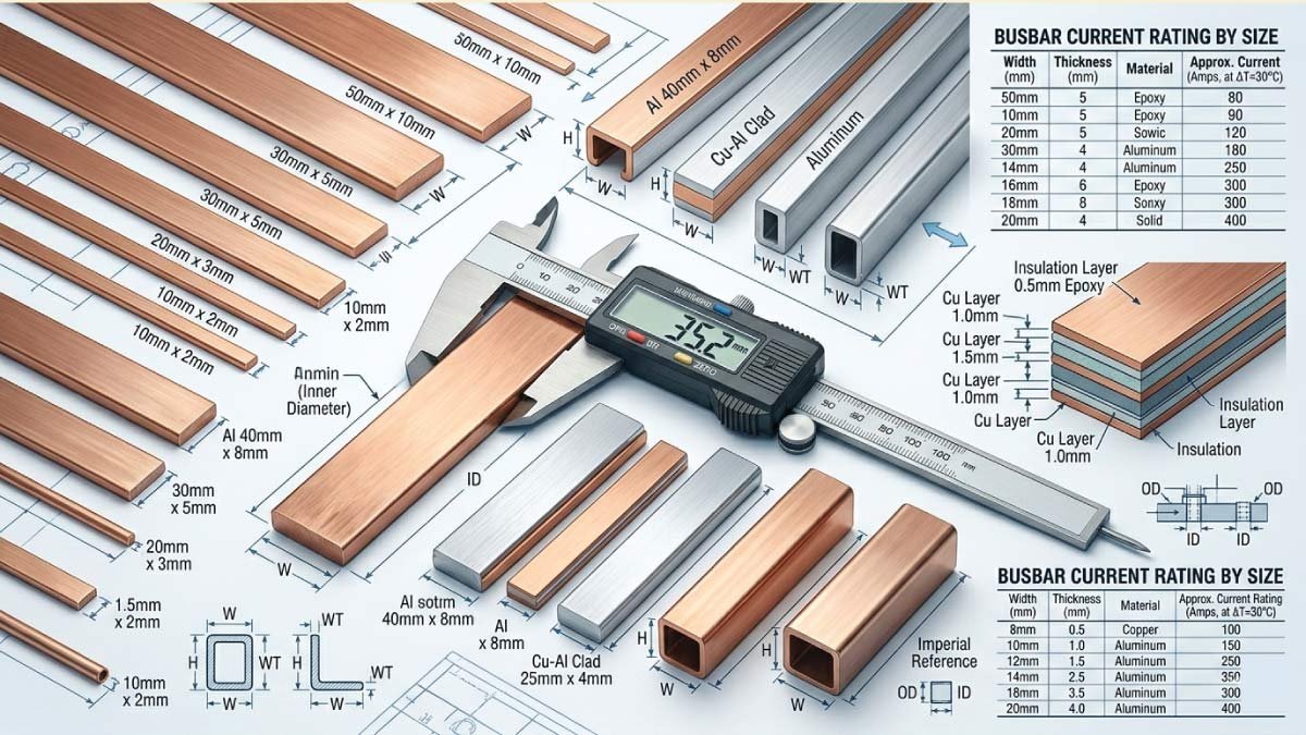
Busbar Size Chart (Copper & Aluminum)
Below is a practical busbar size chart commonly used in electrical engineering applications. These standard dimensions help engineers select the right conductor size based on current demand, temperature rise limits, available installation space, and overall system safety requirements.
Copper Busbar Size Chart
Copper busbars are widely used because they offer excellent electrical conductivity, strong mechanical strength, and good thermal performance. They are commonly preferred in industrial panels, switchboards, and high-current electrical distribution systems.
| Busbar Size (mm) | Cross-Section (mm²) | Current Rating (Approx.) | Typical Use |
|---|---|---|---|
| 10 × 3 mm | 30 mm² | 100–150 A | Small panels, control circuits |
| 12 × 5 mm | 60 mm² | 150–250 A | Light distribution boards |
| 20 × 5 mm | 100 mm² | 250–400 A | Industrial panels |
| 25 × 5 mm | 125 mm² | 300–500 A | Medium load systems |
| 30 × 5 mm | 150 mm² | 400–600 A | Heavy distribution |
| 40 × 5 mm | 200 mm² | 600–800 A | Large switchboards |
| 50 × 10 mm | 500 mm² | 1000–1500 A | Substations, heavy industry |
| 100 × 10 mm | 1000 mm² | 1500–2500 A | High power systems |
Aluminum Busbar Size Chart
Aluminum busbars are lighter and more economical than copper, making them a common choice in large electrical installations. Because aluminum has lower conductivity, larger cross-sectional areas are required to carry the same current safely.
Aluminum has lower conductivity than copper, so larger sizes are required.
| Busbar Size (mm) | Cross-Section (mm²) | Current Rating (Approx.) | Typical Use |
|---|---|---|---|
| 15 × 3 mm | 45 mm² | 80–120 A | Small panels |
| 20 × 5 mm | 100 mm² | 200–300 A | Medium panels |
| 25 × 5 mm | 125 mm² | 250–350 A | Industrial distribution |
| 30 × 10 mm | 300 mm² | 500–700 A | Heavy load systems |
| 50 × 10 mm | 500 mm² | 800–1200 A | Substations |
Copper vs Aluminum Busbars
Copper and aluminum are the two most common materials used for busbars in electrical systems. Each has different electrical, thermal, and mechanical characteristics. The right choice depends on current requirements, available space, installation conditions, and overall project cost.
1. Copper Busbars
Copper is the most widely used busbar material because it offers excellent conductivity, strong mechanical strength, and reliable long-term performance. It is commonly selected for compact electrical panels, industrial switchboards, and systems where space efficiency and thermal performance are important.
Advantages:
- high conductivity
- lower resistance
- better heat handling
- smaller size required
Disadvantages:
- higher cost
- heavier than aluminum
2. Aluminum Busbars
Aluminum is a practical and cost-effective alternative, especially in large electrical installations where weight and material cost are major considerations. Although it requires larger dimensions to carry the same current, it remains widely used in substations and large distribution systems.
Advantages:
- lightweight
- cheaper than copper
- suitable for large systems
Disadvantages:
- lower conductivity
- larger size needed
- more expansion with heat
You May Also Like:
Factors Affecting Busbar Size Selection
Selecting the correct busbar size is essential for electrical safety, thermal stability, and efficient current distribution. Busbar dimensions are determined by electrical load, material properties, cooling conditions, and operating environment. Proper sizing reduces overheating, voltage drop, and long-term reliability problems in electrical systems.
1. Current load
The first step in busbar sizing is calculating the total current the system must carry. Higher current requires a larger cross-sectional area to safely handle electrical flow without overheating. For example, a 100 A system may use a small busbar, 500 A a medium size, and 1000 A or more requires a larger busbar.
2. Material type
Busbar material strongly affects size selection. Copper has higher electrical conductivity than aluminum, so it can carry the same current with a smaller cross-section. Aluminum busbars require larger dimensions for equivalent performance but are often chosen because they are lighter and more economical.
3. Temperature rise
Busbars must operate within safe temperature limits to prevent insulation damage and efficiency loss. As current increases, heat generation also increases. Higher load means higher temperature rise, so larger busbars are often needed to dissipate heat effectively and maintain safe operating conditions.
4. Installation environment
The installation environment affects how well a busbar can release heat. Enclosed panels restrict airflow and cooling, which may require larger busbars. Open installations allow better heat dissipation and may permit smaller sizes. Proper ventilation must always be considered during design.
5. Duty cycle
The duty cycle refers to how long the busbar carries current during operation. Continuous load conditions generate more heat than intermittent operation, so larger busbars are usually required. Correct sizing based on duty cycle improves thermal stability and ensures long-term performance in electrical systems.
You May Also Like:
Common Busbar Shapes
Busbars are available in different shapes depending on space requirements, current capacity, and installation layout. Shape selection affects mechanical strength, routing flexibility, and ease of installation in electrical panels and industrial power systems.
1. Flat busbar
Flat busbars are the most common type used in electrical panels, switchboards, and distribution systems. Their simple shape provides good current carrying capacity, easy mounting, and effective heat dissipation. They are widely preferred in standard industrial and commercial electrical installations.
2. Round busbar
Round busbars are used in specialized electrical systems where better mechanical strength is required. Their shape provides improved structural rigidity and can be beneficial in applications exposed to vibration or mechanical stress. They are less common than flat busbars but useful in certain designs.
3. L-shaped busbar
L-shaped busbars are often used in compact electrical panels where space is limited. Their angled design allows efficient routing around corners and equipment. This makes them useful for space-saving layouts while maintaining reliable electrical connection and current distribution.
4. U-shaped busbar
U-shaped busbars are used in complex routing applications and industrial setups. Their design allows current paths to be arranged around components or through confined spaces. They are helpful where installation flexibility is required while maintaining strong and reliable electrical connections.
Busbar Sizing by Application
Busbar size varies depending on system voltage, current demand, installation environment, and load type. Different applications require different conductor dimensions to ensure safe operation, proper heat dissipation, and long-term electrical reliability under normal and peak load conditions.
1. Residential electrical panels
Residential systems normally use smaller busbars because household electrical loads are relatively moderate. These busbars are designed for compact distribution boards where space is limited but stable power delivery and safety remain important.
Typical size:
- 10 × 3 mm to 20 × 5 mm copper
Used for:
- home distribution boards
- small load circuits
2. Commercial buildings
Commercial electrical installations require larger busbars because they serve lighting systems, office equipment, air conditioning, and other continuous loads. These systems must balance current capacity, heat management, and panel space efficiency.
Typical size:
- 20 × 5 mm to 40 × 5 mm copper
Used for:
- office buildings
- shops
- commercial loads
3. Industrial systems
Industrial systems carry heavier loads and often operate continuously. Larger busbars are required to support machinery, production lines, and motor-driven equipment while maintaining stable voltage and safe operating temperatures.
Typical size:
- 40 × 5 mm to 100 × 10 mm copper
Used for:
- factories
- heavy machinery
- production systems
4. Power substations
Power substations handle very high current and large-scale electrical distribution. These installations often use large copper or aluminum busbars, sometimes arranged in parallel, to achieve high current capacity and reliable thermal performance.
Typical size:
- large copper or aluminum busbars
- multiple parallel bars
Used for:
- high voltage distribution
- grid systems
You May Also Like:
Busbar Ampacity Calculation Basics
Busbar ampacity is an approximate estimate of how much current a conductor can safely carry. It depends on conductor material, cooling conditions, installation layout, and temperature rise limits. Engineers use this as an initial guide before detailed design calculations.
A simple rule of thumb:
Copper busbar:
- 1 mm² ≈ 1.2 to 1.5 A (depending on cooling)
Aluminum busbar:
- 1 mm² ≈ 0.8 to 1.0 A
Example:
- 100 mm² copper busbar ≈ 120–150 A
- 100 mm² aluminum busbar ≈ 80–100 A
Busbar Installation Tips
Proper busbar installation is important for electrical safety, reliable current flow, and long-term system durability. Incorrect installation can lead to overheating, mechanical stress, and connection failure. Following good installation practices helps improve performance, reduce maintenance, and ensure safe operation in electrical panels and industrial systems.
1. Proper spacing
Maintain adequate spacing between busbars to allow proper airflow and heat dissipation. If busbars are installed too close together, heat can build up and increase operating temperature. Correct spacing reduces the risk of overheating and helps maintain stable electrical performance under load.
2. Tight connections
All busbar joints and terminal connections must be securely tightened. Loose connections create electrical resistance, which leads to localized heating, energy loss, and possible damage. Proper tightening ensures strong electrical contact and improves reliability in high-current systems.
3. Surface protection
Aluminum busbars should be protected with anti-oxidation coating because surface oxidation increases contact resistance. This protective layer helps maintain conductivity and improves long-term connection quality. Surface protection is especially important in humid or corrosive environments where oxidation develops more quickly.
4. Proper support
Busbars must be mechanically supported at suitable intervals to prevent movement, sagging, or vibration damage. Good support improves structural stability and protects connections from mechanical stress. This is especially important in industrial systems exposed to vibration or heavy electrical loading.
5. Avoid sharp bends
Sharp bends should be avoided during busbar installation because they create mechanical stress and may reduce conductivity efficiency. Smooth bends help maintain structural strength and allow current to flow more evenly. Proper bending practices also reduce the risk of cracking or long-term fatigue damage.
You May Also Like:
Common Busbar Problems
Even correctly installed busbars can develop problems over time because of load conditions, environmental exposure, or design limitations. Identifying these issues early helps prevent overheating, energy loss, and equipment failure while improving the reliability and safety of the electrical system.
1. Overheating
Overheating is one of the most common busbar problems. It usually happens when the conductor carries more current than its safe capacity or when heat cannot escape effectively. Continuous overheating can damage insulation, reduce efficiency, and shorten equipment life.
Caused by:
- undersized busbar
- poor ventilation
- loose connections
2. Voltage drop
Voltage drop occurs when electrical resistance increases along the length of the busbar. Excessive voltage drop reduces system efficiency and can cause connected equipment to operate below its intended performance level.
Caused by:
- long busbar runs
- insufficient cross-section
3. Oxidation
Oxidation is more common in aluminum busbars because the exposed surface reacts with air and moisture over time. This oxide layer increases contact resistance and gradually reduces conductivity, which can lead to heating and reduced electrical reliability.
- More common in aluminum busbars.
- Reduces conductivity over time.
Quick Busbar Size Reference
| Current Load | Recommended Copper Busbar |
|---|---|
| Up to 100 A | 10 × 3 mm |
| 100–250 A | 20 × 5 mm |
| 250–500 A | 30 × 5 mm |
| 500–800 A | 40 × 5 mm |
| 800–1500 A | 50 × 10 mm |
| 1500+ A | Multiple busbars / custom |
Practical Engineering Insight
In real-world electrical engineering, busbar sizing is not only a matter of calculating current capacity. It is fundamentally about ensuring long-term system reliability, operational safety, and consistent performance under varying load conditions. Engineers must consider both normal and peak operating scenarios when selecting busbar dimensions.
A properly sized busbar ensures:
- stable voltage
- reduced energy loss
- safer operation
- longer system life
In practical industrial environments, even small errors in sizing or assumptions about load can lead to serious consequences such as overheating, voltage instability, equipment damage, or unexpected system shutdowns. This is why busbar design always includes safety margins, thermal considerations, and future load expansion planning.
Common Mistakes in Busbar Selection
Selecting the correct busbar is important for electrical safety, efficiency, and long-term system reliability. Many installation problems occur when only current rating is considered while other design factors are ignored. These mistakes can lead to overheating, energy loss, and reduced system performance.
1. Ignoring heat dissipation
Heat dissipation is a critical factor in busbar sizing. Enclosed electrical panels have limited airflow, which reduces cooling efficiency. If this is ignored, the busbar may operate at higher temperatures than intended. In such installations, larger busbars are often required to safely handle heat buildup.
2. Using aluminum size equal to copper
A common mistake is selecting aluminum busbars with the same dimensions as copper. Aluminum has lower electrical conductivity, so it needs a larger cross-sectional area to carry the same current safely. Correct material-based sizing is essential for efficient and reliable electrical performance.
3. Poor connection design
Poorly designed joints and connection points increase electrical resistance. This creates localized heating, energy loss, and can eventually damage the busbar or surrounding components. Proper connection design with clean contact surfaces and correct tightening is essential for stable current flow and long-term durability.
4. Not considering future load
Electrical systems often expand over time, so future load should be considered during busbar selection. Choosing a busbar only for current demand may limit future upgrades. Designing with extra capacity helps improve flexibility, reduces modification costs, and supports long-term system growth.
Final Thoughts
Busbars play a critical role in modern electrical distribution systems, acting as the main pathways for transmitting and distributing electrical power efficiently. Their size is not just a design detail but a key factor that directly influences system performance, thermal behavior, and overall operational safety in both small and large installations.
The correct busbar size chart helps engineers and electricians select:
- proper cross-sectional area
- correct material (copper or aluminum)
- safe current rating
- reliable installation design
Each of these factors ensures that the electrical system can handle load demands without overheating, excessive voltage drop, or long-term reliability issues.
The key rule is simple:
Always size the busbar based on current load, installation conditions, and safety margin—not just cost.
This approach ensures that the system remains safe under both normal and peak operating conditions while maintaining efficiency and durability.
For most applications, copper busbars provide the best balance of compact size, high conductivity, and strong thermal performance. On the other hand, aluminum busbars are often preferred in large-scale or cost-sensitive projects where weight reduction and material savings are important considerations.
When correctly designed and installed, busbars ensure smooth, safe, and efficient power distribution across any electrical system, making them an essential component of reliable electrical infrastructure.