
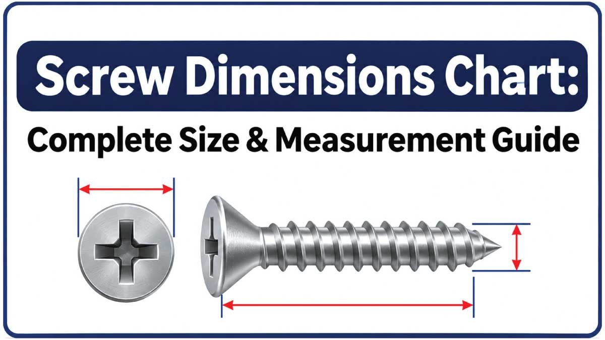
If you need to identify a screw, choose a replacement, or determine whether a fastener will fit a threaded hole, understanding screw dimensions is essential. A screw is not defined by length alone. Diameter, thread pitch, thread type, head diameter, head height, drive size, and overall geometry can all affect fit and performance.
This screw dimensions chart provides a practical reference for common metric and imperial screw sizes, along with explanations of how each measurement is taken. It also covers thread pitch, screw length, head dimensions, common screw types, measurement methods, and tips for selecting the correct fastener.
For standardized metric threads, ISO 262:2023 specifies selected diameter and pitch combinations for commercial fasteners, while ISO 724:2023 defines basic dimensions for ISO metric screw threads. Imperial Unified threads are covered by ASME B1.1, which defines thread forms, series, classes, tolerances, and related dimensions.
What Are Screw Dimensions?
Screw dimensions describe the physical measurements that determine how a screw fits into an application. The most important measurements are nominal diameter, screw length, thread pitch or threads per inch, head diameter, head height, and drive dimensions.
A screw specification may look like:
M6 × 30 mm
This means the screw has a nominal metric diameter of 6 mm and a length of 30 mm. If a pitch is included, such as M6 × 1.0 × 30 mm, the 1.0 mm value identifies the thread pitch.
An imperial screw might be identified as:
1/4-20 × 1 in
Here, 1/4 inch is the nominal diameter, 20 is the number of threads per inch, and 1 inch is the screw length.
It is important to remember that nominal diameter is not always the exact measured outside diameter of the finished screw. Manufacturing tolerances, thread geometry, coatings, and measurement location can affect the actual value.
Main Screw Dimensions to Measure
Before selecting a replacement screw, identify the dimensions that matter for your particular application.
1. Nominal Diameter
The nominal diameter describes the approximate diameter of the screw’s threaded portion.
For metric screws, the diameter is expressed in millimeters:
- M3 = approximately 3 mm nominal diameter
- M4 = approximately 4 mm
- M5 = approximately 5 mm
- M6 = approximately 6 mm
- M8 = approximately 8 mm
- M10 = approximately 10 mm
- M12 = approximately 12 mm
Imperial screws use either a numbered size or a fractional inch diameter.
For example, #8 and #10 are numbered screw sizes, while 1/4 inch and 5/16 inch are fractional sizes.
2. Screw Length
Screw length is usually measured from the bearing surface underneath the head to the end of the screw.
For most pan head, hex head, and button head screws, measure from the underside of the head.
For flat-head or countersunk screws, the head is designed to sit flush with the material, so length is generally measured from the top of the head to the tip.
This distinction is important because two screws with the same threaded length may have different specified overall lengths depending on their head style.
3. Thread Pitch
Metric thread pitch is the distance from one thread crest to the next, measured in millimeters.
For example, an M8 × 1.25 screw has a 1.25 mm pitch.
Imperial threads are normally specified using threads per inch (TPI) rather than pitch.
A higher TPI means the threads are closer together. A lower TPI generally means the threads are farther apart.
4. Head Diameter
Head diameter is the maximum outside diameter of the screw head.
This measurement is especially important when the head must fit inside a clearance, recess, washer, or counterbore.
Head diameter varies considerably between screw types. A pan-head screw, flat-head screw, truss-head screw, and socket-head cap screw should not be assumed to have the same head dimensions even when their thread diameter is identical.
5. Head Height
Head height is the vertical dimension of the head from its bearing surface to its highest point.
Head height can affect:
- Available clearance
- Countersinking requirements
- Overall assembly height
- Tool access
- Flush mounting
Because head geometry differs by standard and screw style, head height should be checked against the manufacturer’s drawing when an exact fit is required.
6. Drive Size
The drive identifies the tool used to install or remove the screw.
Common drive types include:
- Phillips
- Slotted
- Pozidriv
- Torx
- Hex socket
- Square
- Combination drives
The drive size is a separate dimension from thread diameter. An M6 screw, for example, can be manufactured with several different head and drive configurations.
Metric Screw Dimensions Chart
The following chart shows common metric screw diameters and coarse thread pitches. These are common reference sizes rather than a complete dimensional drawing for every screw head style.
| Metric Size | Nominal Diameter (mm) | Common Coarse Pitch (mm) | Typical Identification |
|---|---|---|---|
| M2 | 2.0 | 0.40 | M2 × length |
| M2.5 | 2.5 | 0.45 | M2.5 × length |
| M3 | 3.0 | 0.50 | M3 × length |
| M4 | 4.0 | 0.70 | M4 × length |
| M5 | 5.0 | 0.80 | M5 × length |
| M6 | 6.0 | 1.00 | M6 × length |
| M8 | 8.0 | 1.25 | M8 × length |
| M10 | 10.0 | 1.50 | M10 × length |
| M12 | 12.0 | 1.75 | M12 × length |
| M14 | 14.0 | 2.00 | M14 × length |
| M16 | 16.0 | 2.00 | M16 × length |
| M18 | 18.0 | 2.50 | M18 × length |
| M20 | 20.0 | 2.50 | M20 × length |
ISO standards define metric thread diameter and pitch combinations, including the relationship between selected nominal sizes and thread dimensions.
The pitch values above are commonly used coarse pitches. Fine-pitch versions also exist for many sizes, so an M10 screw should not automatically be assumed to have a 1.5 mm pitch if the application specifies a fine thread.
Common Screw Length Dimensions
Screws are manufactured in many lengths because the correct length depends on the thickness of the materials being joined, required thread engagement, washers, nuts, and the screw design.
A basic length reference for commonly stocked metric screws is shown below.
| Nominal Diameter | Common Lengths (mm) | Example Sizes |
|---|---|---|
| M3 | 6–40 | M3 × 10, M3 × 20, M3 × 30 |
| M4 | 6–50 | M4 × 10, M4 × 25, M4 × 40 |
| M5 | 8–60 | M5 × 12, M5 × 30, M5 × 50 |
| M6 | 10–80 | M6 × 20, M6 × 40, M6 × 60 |
| M8 | 12–100 | M8 × 25, M8 × 50, M8 × 80 |
| M10 | 16–120 | M10 × 30, M10 × 60, M10 × 100 |
| M12 | 20–150 | M12 × 40, M12 × 80, M12 × 120 |
These are common length ranges, not a dimensional standard or guaranteed availability list. Actual available lengths depend on the screw type, manufacturer, standard, material, and application.
Imperial Screw Dimensions Chart
Imperial screws are commonly identified using numbered sizes or fractional diameters. Unified thread specifications use designations such as UNC for Unified National Coarse and UNF for Unified National Fine threads. ASME B1.1 covers Unified inch screw threads and includes dimensional information for different thread series.
| Screw Size | Nominal Diameter (in) | Common Coarse Thread | Common Fine Thread |
|---|---|---|---|
| #2 | 0.086 | 32 TPI | 56 TPI |
| #4 | 0.112 | 40 TPI | 48 TPI |
| #6 | 0.138 | 32 TPI | 40 TPI |
| #8 | 0.164 | 32 TPI | 36 TPI |
| #10 | 0.190 | 24 TPI | 32 TPI |
| 1/4 in | 0.250 | 20 TPI | 28 TPI |
| 5/16 in | 0.3125 | 18 TPI | 24 TPI |
| 3/8 in | 0.375 | 16 TPI | 24 TPI |
| 7/16 in | 0.4375 | 14 TPI | 20 TPI |
| 1/2 in | 0.500 | 13 TPI | 20 TPI |
The table provides common UNC and UNF reference combinations. Exact thread selection should be verified against the applicable screw standard when a specific tolerance or fit is required.
Screw Head Dimensions by Type
Thread dimensions alone do not fully describe a screw. The head style can substantially change the screw’s dimensions and installation requirements.
Pan Head Screws
Pan-head screws have a rounded top with a relatively broad bearing surface. They are commonly used for general fastening applications.
Important dimensions include:
- Head diameter
- Head height
- Thread diameter
- Screw length
- Drive size
Flat-Head or Countersunk Screws
Flat-head screws are designed to sit flush with or below the surface of the material when installed in a properly prepared countersunk hole.
Their dimensions include:
- Head diameter
- Countersink angle
- Head height
- Thread diameter
- Overall length
- Drive size
The countersink angle and head geometry are particularly important because different standards can specify different designs.
Socket Head Cap Screws
Socket head cap screws have a cylindrical head and an internal hexagonal drive.
Typical dimensions include:
- Thread diameter
- Screw length
- Head diameter
- Head height
- Hex socket size
- Thread pitch
They are frequently selected where a compact head and high-strength fastening arrangement are useful.
Button Head Screws
Button-head screws have a rounded, low-profile head. Their head dimensions differ from socket head cap screws even when both use an internal hex drive.
Truss Head Screws
Truss-head screws have a broad head with a relatively low profile. The larger bearing area can be useful for sheet material and applications where distributing the load over a larger area is desirable.
Also Read:
How to Measure Screw Dimensions
If the original screw has no readable marking, you can determine most important dimensions with a caliper, thread gauge, ruler, or pitch gauge.
Step 1: Measure the Diameter
Place the caliper across the threaded portion and measure the outside diameter.
For a metric screw, a measurement close to 6 mm suggests an M6 nominal size, while a measurement close to 8 mm suggests M8.
Do not identify the thread solely from diameter. Different thread standards can have similar nominal diameters.
Step 2: Measure the Length
Measure from the correct reference point under the head for non-countersunk screws.
For countersunk screws, measure from the top of the head to the tip.
Write the result in the same unit used for the replacement screw.
Step 3: Determine the Thread Pitch
For metric screws, use a metric thread pitch gauge or measure the distance across several threads and divide by the number of intervals.
For imperial screws, determine threads per inch (TPI).
For example, if 20 complete thread intervals occupy one inch, the screw is 20 TPI.
Step 4: Measure the Head
If head clearance is important, measure:
- Head diameter
- Head height
- Drive width or socket size
- Countersink angle, when applicable
For precision applications, compare these measurements with the manufacturer’s dimensional drawing rather than relying on a generic chart.
Also Read:
How Screw Size Is Written
Understanding screw designations makes it much easier to interpret a fastener specification.
Metric Example
M8 × 40
Means:
- M = metric thread
- 8 = nominal diameter of 8 mm
- 40 = nominal screw length of 40 mm
If written as:
M8 × 1.25 × 40
The additional 1.25 identifies the thread pitch.
Imperial Example
1/4-20 × 1
Means:
- 1/4 = nominal diameter
- 20 = threads per inch
- 1 = screw length in inches
A designation may also include a thread series such as UNC or UNF, plus a material, grade, coating, or other specification.
Metric vs Imperial Screw Dimensions
Metric and imperial screws should not be treated as interchangeable simply because their diameters appear similar.
| Feature | Metric Screws | Imperial Screws |
|---|---|---|
| Diameter | Millimeters | Inches or numbered sizes |
| Thread specification | Pitch in mm | Threads per inch |
| Example | M6 × 1.0 | 1/4-20 |
| Common systems | ISO metric | Unified inch |
| Length | Usually mm | Usually inches |
| Thread identification | Diameter + pitch | Diameter + TPI |
For example, an M6 screw and a 1/4-inch screw have relatively similar nominal diameters, but their threads are not automatically compatible.
Trying to force a near-matching metric and imperial screw into a threaded hole can damage the threads and compromise the connection.
Also Read:
How to Choose the Correct Screw Size
Choosing the correct screw involves more than matching the diameter.
Consider these factors:
- Thread diameter: Match the mating thread or required pilot-hole specification.
- Thread pitch: The screw must match the internal thread when fastening into a tapped hole.
- Length: Select enough engagement without excessive penetration.
- Head style: Make sure the head suits the mounting surface.
- Drive type: Confirm that the installation tool fits.
- Material: Select a material appropriate for strength, corrosion resistance, temperature, and environment.
- Thread type: Confirm metric, UNC, UNF, self-tapping, wood screw, or another relevant thread system.
- Clearance: Check whether the head and shaft fit within the available space.
- Washer compatibility: If using a washer, make sure the screw head and washer dimensions are compatible.
- Application requirements: Structural, machinery, automotive, electrical, woodworking, and sheet-metal applications can require different fastener designs.
For critical assemblies, the manufacturer’s specification or applicable fastener standard should take priority over a general size chart.
Common Screw Measurement Mistakes
Incorrect identification often happens because only one dimension is checked.
Mistake 1: Measuring Only the Length
Two screws can have the same length but completely different diameters or thread pitches.
Mistake 2: Assuming Diameter Determines the Thread
A screw measuring approximately 8 mm across does not automatically tell you whether it has the required pitch.
Mistake 3: Confusing Metric and Imperial Threads
M6 and 1/4-inch screws are close enough in nominal diameter to cause confusion, but that does not make them interchangeable.
Mistake 4: Measuring a Countersunk Screw Incorrectly
Countersunk screws should generally be measured from the top of the head when determining their specified overall length.
Mistake 5: Ignoring Head Dimensions
A screw may have the correct thread diameter and length but still fail to fit because the head is too large or the drive does not provide adequate clearance.
Mistake 6: Assuming Every M6 Screw Has the Same Head
The M6 designation identifies the nominal metric thread size, not a universal head shape or head dimension.
Screw Dimensions and Thread Standards
Screw dimensions are influenced by the applicable standard. Metric general-purpose screw threads are governed by a family of ISO standards covering basic dimensions, selected sizes, and tolerances.
ISO 262:2023 specifies selected metric diameter-and-pitch combinations for bolts, screws, studs, and nuts, while ISO 724:2023 specifies basic dimensions for ISO general-purpose metric screw threads.
Thread tolerances are a separate consideration. ISO 965 standards address limits and tolerances for metric thread dimensions, meaning two screws with the same nominal diameter and pitch can still have specified tolerance differences.
For Unified inch threads, ASME B1.1 specifies thread forms, series, classes, allowances, and tolerances for UN and UNR thread forms.
This is why a general screw size chart is useful for identification, but engineering drawings and applicable standards should be used for precision or safety-critical work.
Quick Screw Measurement Checklist
When identifying an unknown screw, record the following information:
- Nominal diameter
- Screw length
- Thread pitch or TPI
- Thread type
- Head style
- Head diameter
- Head height
- Drive type
- Drive size
- Material or grade, when relevant
- Coating or finish, when relevant
- Manufacturer or standard marking, if available
Once these details are known, identifying a replacement becomes much easier.
Frequently Asked Questions About Screw Dimensions
What are the most important screw dimensions?
The most important dimensions are diameter, length, thread pitch or TPI, head dimensions, and drive size. The exact priorities depend on the application.
How is screw length measured?
For most screws with projecting heads, length is measured from the underside of the head to the tip. Countersunk screws are commonly measured from the top of the head to the tip.
What does M6 mean on a screw?
M6 indicates a metric screw with a nominal thread diameter of 6 mm. It does not by itself specify the screw’s length, head type, drive, material, or pitch.
What does M8 × 1.25 mean?
M8 indicates an 8 mm nominal diameter, while 1.25 indicates a 1.25 mm thread pitch. The screw length would normally be provided separately.
Is an M6 screw the same as a 1/4-inch screw?
No. Their nominal diameters are relatively close, but their thread dimensions differ. They should not be substituted without verifying the actual thread compatibility.
How do I know what screw size I have?
Measure the diameter and length, then identify the thread pitch using a thread gauge or by carefully measuring multiple threads. Also check the head style and drive.
Does screw head size depend on thread diameter?
Not necessarily. Screw head dimensions depend on the screw type, applicable standard, manufacturer, and design. The same thread diameter can be available with different head styles and dimensions.
Conclusion
A screw dimensions chart is useful for quickly identifying the measurements that matter, but selecting the correct fastener requires more than matching diameter and length. Thread pitch, screw length, head dimensions, drive type, material, and applicable standards can all affect whether a screw is suitable.
For metric fasteners, start with the nominal M-size and verify the pitch. For imperial fasteners, identify the nominal diameter and threads per inch. Then check the screw head, length, drive, and application requirements.
For general repairs and hardware identification, a caliper and thread gauge can provide most of the information you need. For precision machinery or safety-critical assemblies, always verify the complete dimensional specification against the applicable standard or manufacturer’s documentation.