
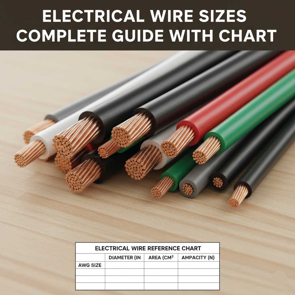
Choosing the correct electrical wire size is essential for safe, reliable electrical installations. Wire that is too small for the amount of current flowing through it can overheat, while unnecessarily large wire can increase cost and make installation more difficult.
An electrical wire size chart helps you compare American Wire Gauge (AWG) sizes, conductor diameter, cross-sectional area, and typical ampacity. However, wire selection is not based on gauge alone. The conductor material, insulation temperature rating, installation conditions, circuit length, voltage drop, and applicable electrical code can all affect the final choice.
This guide explains common electrical wire sizes, their approximate dimensions, typical current-carrying capacities, and practical applications. Use the charts as a reference, but always verify the requirements for the specific installation before selecting or installing electrical wiring.
What Is Electrical Wire Size?
Electrical wire size describes the size of the conductor inside a cable or wire. In North America, conductor sizes are commonly identified using the American Wire Gauge (AWG) system.
One important feature of AWG is that the numbering works in reverse:
- A smaller AWG number means a larger conductor.
- A larger AWG number means a smaller conductor.
- Larger conductors generally have lower electrical resistance.
- Lower resistance allows a conductor to carry more current under the appropriate conditions.
For example, 10 AWG wire is substantially larger than 14 AWG wire. Likewise, 6 AWG is larger than 10 AWG.
Wire size is important because electrical current produces heat as it passes through resistance. A properly sized conductor can carry the intended load without exceeding its permitted temperature when installed under the conditions for which it is rated.
Electrical Wire Size Chart
The following chart provides common copper conductor sizes used in electrical work. Diameter and area values are approximate and refer to the conductor itself rather than the complete insulated cable.
| AWG Size | Diameter (mm) | Area (mm²) | Approx. Area (in²) |
|---|---|---|---|
| 14 AWG | 1.63 mm | 2.08 mm² | 0.00323 |
| 12 AWG | 2.05 mm | 3.31 mm² | 0.00513 |
| 10 AWG | 2.59 mm | 5.26 mm² | 0.00815 |
| 8 AWG | 3.26 mm | 8.37 mm² | 0.01297 |
| 6 AWG | 4.11 mm | 13.3 mm² | 0.0206 |
| 4 AWG | 5.19 mm | 21.2 mm² | 0.0328 |
| 3 AWG | 5.83 mm | 26.7 mm² | 0.0413 |
| 2 AWG | 6.54 mm | 33.6 mm² | 0.0521 |
| 1 AWG | 7.35 mm | 42.4 mm² | 0.0657 |
| 1/0 AWG | 8.25 mm | 53.5 mm² | 0.0829 |
| 2/0 AWG | 9.27 mm | 67.4 mm² | 0.1045 |
| 3/0 AWG | 10.4 mm | 85.0 mm² | 0.1318 |
| 4/0 AWG | 11.7 mm | 107.2 mm² | 0.1662 |
As the AWG number decreases, the conductor becomes physically larger. Once the system reaches sizes larger than 1 AWG, the designation changes to 1/0, 2/0, 3/0, and 4/0.
Common Electrical Wire Sizes and Their Uses
Different wire gauges are suited to different types of circuits. The actual selection depends on the load, protection, installation method, and applicable code.
14 AWG Wire
14 AWG copper wire is commonly associated with smaller branch circuits, particularly circuits protected at 15 amps where permitted by the applicable electrical code.
It is frequently found in lighting and general-purpose residential circuits.
12 AWG Wire
12 AWG is larger than 14 AWG and is commonly used for 20-amp branch circuits where permitted.
Typical applications can include general-purpose receptacle circuits, kitchen circuits, utility areas, and other higher-load branch circuits.
10 AWG Wire
10 AWG is commonly used for circuits requiring more current than typical 12 AWG applications.
It may be used for certain 30-amp circuits, equipment, appliances, and longer circuit runs where voltage drop needs additional consideration.
8 AWG Wire
8 AWG provides substantially more conductor area than 10 AWG. It is often encountered in larger equipment circuits, feeders, and applications with higher electrical loads.
6 AWG and Larger
6 AWG, 4 AWG, 3 AWG, 2 AWG, 1 AWG, and larger conductors are used when the electrical load, feeder capacity, equipment requirements, or installation conditions call for larger conductors.
These sizes are more common in feeders, larger equipment, service-related applications, and other high-current installations.
Electrical Wire Ampacity Chart
Ampacity means the maximum current a conductor can carry continuously under specified conditions without exceeding its permitted temperature.
Ampacity should never be treated as a universal value for every installation. The permitted current depends on factors such as conductor material, insulation temperature rating, ambient temperature, number of current-carrying conductors, installation method, and applicable electrical code.
For common copper conductors, the following values are useful as a general reference for conductors under typical code-based conditions. They should not replace the requirements for a specific installation.
| Copper Wire Size | 60°C Reference | 75°C Reference | Typical Residential Association |
|---|---|---|---|
| 14 AWG | 15 A | 20 A | 15 A circuits |
| 12 AWG | 20 A | 25 A | 20 A circuits |
| 10 AWG | 30 A | 35 A | 30 A circuits |
| 8 AWG | 40 A | 50 A | Higher-load circuits |
| 6 AWG | 55 A | 65 A | Feeders/equipment |
| 4 AWG | 70 A | 85 A | Larger feeders |
| 3 AWG | 85 A | 100 A | Larger feeders |
| 2 AWG | 95 A | 115 A | High-current feeders |
| 1 AWG | 110 A | 130 A | High-current feeders |
| 1/0 AWG | 125 A | 150 A | Large feeders |
| 2/0 AWG | 145 A | 175 A | Large feeders |
| 3/0 AWG | 165 A | 200 A | Large feeders |
| 4/0 AWG | 195 A | 230 A | Very large feeders |
The values above are reference ampacities, not automatic circuit-breaker recommendations. Small-conductor rules, equipment ratings, terminal temperature limitations, correction factors, and other code requirements can change the allowable installation.
How Wire Gauge Affects Current Capacity
A larger conductor generally has less electrical resistance than a smaller conductor made from the same material.
When current flows through resistance, heat is produced. Increasing conductor size reduces resistance and helps manage the heat associated with current flow.
For example, 12 AWG copper has a larger cross-sectional area than 14 AWG copper. This is one reason 12 AWG is commonly associated with higher-current branch circuits.
However, it would be incorrect to choose a wire solely because its gauge appears large enough. The complete electrical system must be considered.
Important factors include:
- Circuit load
- Breaker or fuse rating
- Conductor material
- Insulation temperature rating
- Ambient temperature
- Number of current-carrying conductors
- Installation method
- Circuit length
- Voltage drop
- Equipment terminals
- Applicable electrical code
Copper vs. Aluminum Wire Size
Copper and aluminum are both used as electrical conductors, but they do not perform identically.
Copper has lower electrical resistivity than aluminum, so an aluminum conductor generally needs a larger cross-sectional area to provide similar electrical performance for a given application.
| Feature | Copper | Aluminum |
|---|---|---|
| Conductivity | Higher | Lower |
| Typical conductor size for equivalent load | Smaller | Larger |
| Weight | Heavier | Lighter |
| Common use | Branch circuits and equipment | Feeders and larger conductors |
| Connection requirements | Standard approved terminals | Requires compatible terminals/connectors |
Aluminum wiring must be used with equipment, terminals, and connectors approved for aluminum conductors. The connection method is particularly important because aluminum and copper have different physical and electrical characteristics.
Never substitute one conductor material for another simply because the gauge number appears similar.
Metric Wire Size vs. AWG
Many countries identify conductor size using square millimeters rather than AWG.
The metric measurement normally describes the conductor’s cross-sectional area, such as 1.5 mm², 2.5 mm², 4 mm², or 6 mm².
AWG and metric sizes do not always match exactly. A metric size may fall between two AWG sizes, so an equivalent should be treated as a comparison rather than an exact conversion.
| Common AWG | Approx. Conductor Area | Approximate Metric Comparison |
|---|---|---|
| 14 AWG | 2.08 mm² | 2.0–2.5 mm² range |
| 12 AWG | 3.31 mm² | 3.0–4.0 mm² range |
| 10 AWG | 5.26 mm² | 6 mm² range |
| 8 AWG | 8.37 mm² | 10 mm² range |
| 6 AWG | 13.3 mm² | 16 mm² range |
| 4 AWG | 21.2 mm² | 25 mm² range |
| 2 AWG | 33.6 mm² | 35 mm² range |
| 1/0 AWG | 53.5 mm² | 50–70 mm² range |
| 4/0 AWG | 107.2 mm² | 95–120 mm² range |
These are approximate comparisons. When replacing or specifying wiring, use the conductor size required by the applicable electrical standard rather than selecting the nearest metric or AWG number automatically.
How to Choose the Correct Electrical Wire Size
Selecting wire size should be treated as a process rather than a simple chart lookup.
1. Determine the Electrical Load
Start by identifying the equipment or circuit load.
For resistive loads, the relationship between power, voltage, and current can be expressed as:
Current = Power ÷ Voltage
For example, a 2,400-watt load operating at 120 volts draws approximately 20 amps under ideal conditions.
Real installations may require additional considerations, including continuous loads and equipment-specific requirements.
2. Select the Appropriate Circuit Protection
The conductor must be properly protected by the circuit’s overcurrent protection.
A larger wire does not automatically make it acceptable to install a larger breaker. The breaker, conductor, equipment, and installation must be compatible.
3. Check the Conductor Material
Confirm whether the conductor is copper or aluminum. Do not assume that the same AWG size has identical characteristics regardless of material.
4. Check the Insulation Rating
Wire insulation has a temperature rating. Common ratings include 60°C, 75°C, and 90°C.
The temperature rating used for ampacity calculations can depend on the conductor, equipment terminals, and applicable code.
5. Consider Circuit Length
A circuit that is electrically adequate at a short distance may experience noticeable voltage drop over a much longer run.
Long circuits may require a larger conductor to keep voltage drop within an acceptable range.
Also Read:
Wire Size and Voltage Drop
Voltage drop occurs when electrical resistance in the circuit causes the voltage available at the load to be lower than the source voltage.
It becomes more significant as:
- Wire length increases
- Current increases
- Conductor size decreases
- Conductor resistance increases
For this reason, a long run may require a larger wire even when the basic ampacity calculation suggests a smaller conductor could carry the load.
Voltage drop is particularly important for motors, lighting, sensitive electronics, and equipment operating over long distances.
A useful rule is that wire selection involves both ampacity and performance. A conductor must be able to safely carry the current and, where necessary, maintain acceptable voltage at the load.
Solid Wire vs. Stranded Wire
Wire construction also matters.
Solid Wire
Solid wire contains one continuous conductor.
Advantages include:
- Simple construction
- Easy termination in many fixed installations
- Good mechanical stability
- Common use in building wiring
Stranded Wire
Stranded wire contains multiple smaller wires grouped together.
Advantages include:
- Greater flexibility
- Easier routing around equipment
- Useful for vibration-prone applications
- Common in equipment wiring, control wiring, and flexible cords
Two conductors can have similar electrical cross-sectional areas while behaving differently mechanically because of their construction.
Also Read:
Common Electrical Wire Size Mistakes
Choosing a wire based only on the number printed on its insulation is one of the most common mistakes.
Avoid these errors:
- Assuming a smaller AWG number means a smaller wire.
- Choosing wire solely from a basic ampacity table.
- Ignoring conductor length.
- Forgetting voltage drop on long runs.
- Treating copper and aluminum as interchangeable.
- Ignoring insulation temperature ratings.
- Installing a larger circuit breaker simply because larger wire is available.
- Ignoring the number of current-carrying conductors in a raceway or cable.
- Using connectors that are not approved for the conductor material.
- Assuming every 12 AWG or 10 AWG installation has the same allowable ampacity.
- Selecting wire without checking the applicable electrical code.
A chart is a starting point, not a substitute for the complete electrical design requirements.
Also Read:
Quick Electrical Wire Size Reference
For a fast comparison, this simplified table shows common AWG sizes and their typical applications.
| Wire Size | Conductor Diameter | Common Reference Use |
|---|---|---|
| 14 AWG | 1.63 mm | Smaller branch circuits |
| 12 AWG | 2.05 mm | General 20 A branch circuits |
| 10 AWG | 2.59 mm | Higher-load branch circuits |
| 8 AWG | 3.26 mm | Larger equipment/feeders |
| 6 AWG | 4.11 mm | Larger equipment/feeders |
| 4 AWG | 5.19 mm | Large feeders |
| 2 AWG | 6.54 mm | High-current feeders |
| 1/0 AWG | 8.25 mm | Large feeders |
| 2/0 AWG | 9.27 mm | High-capacity feeders |
| 4/0 AWG | 11.7 mm | Very large conductors |
These application descriptions are intentionally broad because the correct wire size depends on the actual installation.
Frequently Asked Questions
What wire size is commonly used for a 15-amp circuit?
14 AWG copper is commonly associated with 15-amp branch circuits where permitted by the applicable electrical code. The complete installation still needs to meet local requirements.
What wire size is commonly used for a 20-amp circuit?
12 AWG copper is commonly used for 20-amp branch circuits. Installation conditions, conductor temperature ratings, and code requirements still need to be considered.
Is 10 AWG wire larger than 12 AWG?
Yes. 10 AWG has a larger conductor diameter and greater cross-sectional area than 12 AWG. Remember that AWG numbers decrease as conductor size increases.
Does a longer wire run require a larger wire?
It can. Longer runs increase voltage drop, so a larger conductor may be appropriate even when the smaller conductor has sufficient basic ampacity.
Is copper wire better than aluminum wire?
Neither material is automatically better for every application. Copper has higher conductivity, while aluminum is lighter and commonly used for larger conductors. The conductor and connection system must be designed for the selected material.
What does AWG mean on electrical wire?
AWG stands for American Wire Gauge. It is a standardized system used to identify the diameter of electrical conductors.
Can I use a larger wire than required?
A larger conductor can sometimes be used, but the entire installation must remain compatible with the terminals, connectors, raceway, equipment, bending requirements, and applicable code. Larger wire does not justify using a larger breaker without proper design.
Does wire size determine ampacity by itself?
No. Wire size is important, but ampacity also depends on conductor material, insulation rating, ambient conditions, installation method, number of current-carrying conductors, and other applicable requirements.
What is the difference between wire size and cable size?
Wire size generally refers to the individual conductor. Cable size can refer to an assembly containing multiple insulated conductors and possibly a grounding conductor. The outside dimensions of a cable can therefore be much larger than the conductor size shown on a wire chart.
Conclusion
An electrical wire size chart is a useful starting point for comparing AWG numbers, conductor diameter, cross-sectional area, and common applications. The most important AWG rule to remember is that a lower AWG number represents a larger conductor.
For a safe selection, consider the electrical load, overcurrent protection, conductor material, insulation rating, circuit length, voltage drop, installation conditions, and applicable electrical code together. A 12 AWG conductor, for example, should not automatically be treated as suitable for every 20-amp situation simply because that combination is common.
Use the chart to understand wire sizes and narrow down the appropriate conductor, then verify the final selection against the requirements of the actual electrical installation.