
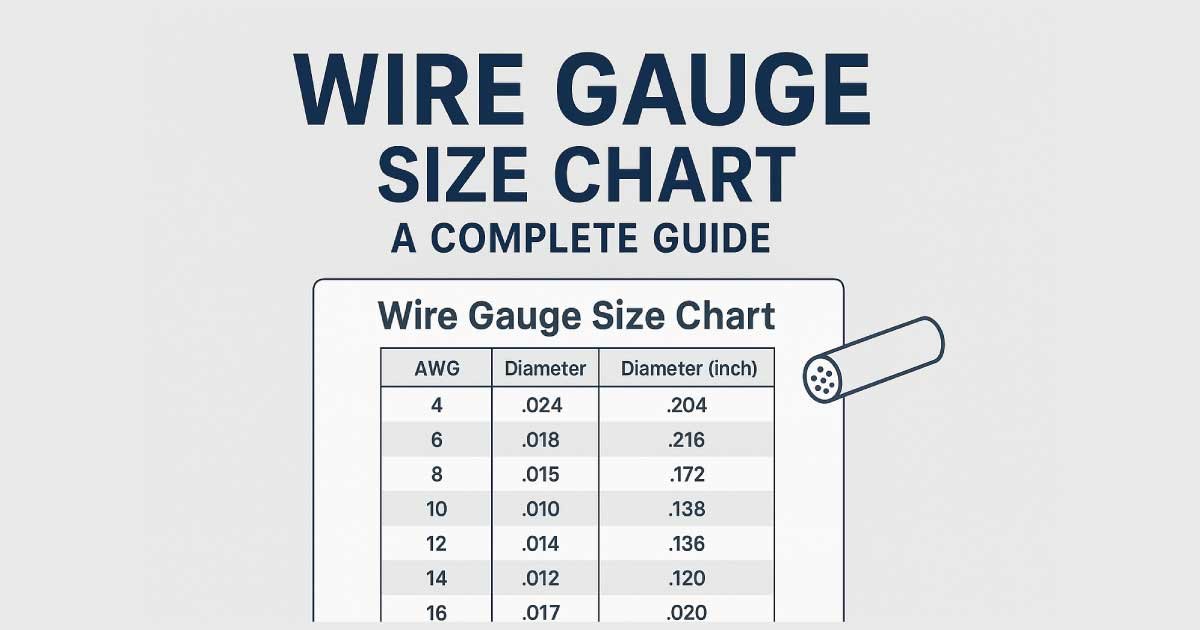
Choosing the correct wire size is important for electrical performance, voltage drop, heat management, and safe operation. The wire gauge size chart is one of the quickest ways to compare conductor sizes, but wire gauge numbers can be confusing because a smaller AWG number means a larger wire.
American Wire Gauge, or AWG, is commonly used for electrical wire sizes in North America. Each gauge corresponds to a defined conductor diameter and cross-sectional area. As the gauge number decreases, the conductor becomes larger, resistance decreases, and the conductor can generally carry more current under comparable conditions.
This guide explains common AWG sizes, wire diameter, cross-sectional area, resistance, metric equivalents, ampacity considerations, and how to choose the right wire gauge for an application. Because allowable current depends on insulation, conductor material, temperature, installation method, and applicable electrical code, the gauge alone should never be treated as a universal ampacity rating.
What Is Wire Gauge?
Wire gauge is a standardized way of describing the diameter of a conductor. In the American Wire Gauge (AWG) system, gauge numbers become smaller as wire diameter increases.
For example:
- 18 AWG is smaller than 14 AWG.
- 14 AWG is smaller than 10 AWG.
- 10 AWG is smaller than 6 AWG.
- 6 AWG is smaller than 2 AWG.
- Sizes larger than 1 AWG are commonly written as 1/0, 2/0, 3/0, and 4/0.
The AWG system applies a geometric progression rather than a simple linear increase. This means the difference between consecutive gauge sizes represents a predictable change in conductor diameter and cross-sectional area.
Southwire explains the basic relationship clearly: as the AWG number decreases, conductor size increases, which reduces resistance and can increase the amount of power that can be transferred by the conductor.
Wire Gauge Size Chart
The following chart provides common solid-conductor AWG dimensions. Diameter and cross-sectional area describe the conductor itself, not the complete insulated cable.
| AWG Size | Diameter (mm) | Diameter (in) | Area (mm²) | Resistance Approx. (Ω/km at 20°C) |
|---|---|---|---|---|
| 24 | 0.511 | 0.0201 | 0.205 | 84.2 |
| 22 | 0.644 | 0.0253 | 0.326 | 52.9 |
| 20 | 0.812 | 0.0320 | 0.518 | 33.3 |
| 18 | 1.024 | 0.0403 | 0.823 | 20.9 |
| 16 | 1.291 | 0.0508 | 1.31 | 13.2 |
| 14 | 1.628 | 0.0641 | 2.08 | 8.28 |
| 12 | 2.053 | 0.0808 | 3.31 | 5.21 |
| 10 | 2.588 | 0.1019 | 5.26 | 3.28 |
| 8 | 3.264 | 0.1285 | 8.37 | 2.06 |
| 6 | 4.115 | 0.1620 | 13.3 | 1.30 |
| 4 | 5.189 | 0.2043 | 21.2 | 0.815 |
| 3 | 5.827 | 0.2294 | 26.7 | 0.646 |
| 2 | 6.544 | 0.2576 | 33.6 | 0.513 |
| 1 | 7.348 | 0.2893 | 42.4 | 0.407 |
| 1/0 | 8.251 | 0.3249 | 53.5 | 0.322 |
| 2/0 | 9.266 | 0.3648 | 67.4 | 0.255 |
| 3/0 | 10.40 | 0.4096 | 85.0 | 0.203 |
| 4/0 | 11.68 | 0.4600 | 107.2 | 0.161 |
Resistance values can vary slightly depending on conductor material, temperature, construction, and whether the conductor is solid or stranded. Manufacturer specifications should be used when an exact resistance value is required.
For comparison, Southwire’s conductor data shows the same general trend: 14 AWG has substantially higher resistance than 12 AWG, while 10 AWG has lower resistance than both.
How AWG Wire Sizes Work
AWG can seem backward at first because the number gets smaller as the wire gets larger.
Smaller AWG Means Larger Wire
Consider these common sizes:
14 AWG → 12 AWG → 10 AWG → 8 AWG → 6 AWG
Moving from left to right means the conductor becomes physically larger.
A larger conductor generally has:
- Lower electrical resistance
- Greater cross-sectional area
- Greater current-carrying capability under comparable conditions
- Lower voltage drop for a given current and length
However, this does not mean you can determine the safe current for a wire from its AWG number alone.
What Happens as Wire Gets Larger?
A larger conductor provides more cross-sectional area for electrical current.
Because resistance is related to conductor length and cross-sectional area, increasing the conductor area reduces resistance when the material and temperature are otherwise comparable.
This is particularly important for long cable runs, where voltage drop can become significant.
Wire Gauge and Cross-Sectional Area
Cross-sectional area is often expressed in mm² in metric systems and is useful when comparing AWG with metric conductor sizes.
There is not a perfect one-to-one conversion between AWG and metric wire sizes. Southwire specifically notes that AWG/kcmil and metric sizes do not have a direct equivalency; published comparisons identify the closest sizes rather than declaring the systems identical.
A useful comparison is:
| AWG | Approx. Area (mm²) | Closest Common Metric Size |
|---|---|---|
| 14 | 2.08 | 2.5 mm² |
| 12 | 3.31 | 4 mm² |
| 10 | 5.26 | 6 mm² |
| 8 | 8.37 | 10 mm² |
| 6 | 13.3 | 16 mm² |
| 4 | 21.2 | 25 mm² |
| 2 | 33.6 | 35 mm² |
| 1/0 | 53.5 | 50 mm² |
| 2/0 | 67.4 | 70 mm² |
| 3/0 | 85.0 | 95 mm² |
| 4/0 | 107.2 | 120 mm² |
These are closest-size comparisons, not exact conversions. The metric size can have a slightly different cross-sectional area from the AWG conductor.
Common Wire Gauge Sizes and Applications
Different wire gauges are commonly encountered in different types of electrical work.
24–22 AWG
These are relatively small conductors and are commonly found in low-current electronics, signal wiring, communication applications, and control circuits.
They are not automatically suitable for power applications simply because the voltage may be low. Current, conductor length, insulation, and equipment requirements still matter.
20–18 AWG
These sizes are frequently used for smaller control circuits, electronics, instrumentation, and low-current wiring.
18 AWG is larger than 20 AWG and therefore has lower resistance for the same conductor material and length.
16–14 AWG
These are common medium-small wire sizes.
14 AWG is frequently encountered in building-wire applications, while 16 AWG is common in various equipment, control, and flexible-cord applications.
The exact permitted application depends on the wire type, insulation rating, installation method, and applicable electrical requirements.
12–10 AWG
These are substantially larger conductors used where more current or reduced voltage drop is required.
12 AWG and 10 AWG are common sizes in branch-circuit and equipment applications, but their allowable ampacity depends on the complete installation.
8–4 AWG
These larger conductors are used for higher-current equipment, feeders, battery systems, machinery, and other applications where a larger conductor is necessary.
At these sizes, cable flexibility, termination requirements, conduit capacity, bending radius, and installation conditions become increasingly important.
2 AWG and Larger
Sizes such as 2 AWG, 1 AWG, 1/0, 2/0, 3/0, and 4/0 are used for high-current applications.
Once conductors reach these sizes, they are often selected based on detailed electrical calculations rather than a simple household wire-size rule.
Wire Gauge vs. Ampacity
Ampacity is the maximum current a conductor is permitted to carry under specified conditions.
It is important to understand that AWG size and ampacity are not the same thing.
The same AWG conductor can have different allowable ampacity values depending on:
- Conductor material
- Insulation temperature rating
- Ambient temperature
- Number of current-carrying conductors
- Installation method
- Raceway or cable configuration
- Terminal temperature limitations
- Applicable electrical code
For example, Southwire’s published ampacity tables show different values for copper and aluminum conductors and for different insulation temperature ratings.
Therefore, a chart that simply says “12 AWG = X amps” can be misleading without identifying the conditions behind that value.
Common Copper Wire Ampacity Examples
For common copper building-wire sizes, Southwire’s published table based on NEC requirements lists the following basic values for several insulation temperature categories. These values are presented as code-based reference information, not as universal ratings for every installation.
| Copper AWG | 60°C (A) | 75°C (A) | 90°C (A) |
|---|---|---|---|
| 14 | 15 | 20* | 25* |
| 12 | 20 | 25 | 30 |
| 10 | 30 | 35 | 40 |
| 8 | 40 | 50 | 55 |
| 6 | 55 | 65 | 75 |
| 4 | 70 | 85 | 95 |
| 3 | 85 | 100 | 110 |
| 2 | 95 | 115 | 130 |
| 1 | 110 | 130 | 145 |
| 1/0 | 125 | 150 | 170 |
| 2/0 | 145 | 175 | 195 |
| 3/0 | 165 | 200 | 225 |
| 4/0 | 195 | 230 | 260 |
*The table source notes that additional overcurrent-protection limitations apply to 14, 12, and 10 AWG copper conductors under NEC requirements. Other installation rules can also affect the final allowable value.
This demonstrates why wire gauge should be treated as one part of conductor selection rather than a complete electrical-sizing calculation.
Also Read:
Wire Gauge and Resistance
Resistance is one of the most useful technical characteristics to understand when comparing wire gauges.
For a conductor made from the same material and operating under comparable conditions:
Larger wire → larger cross-sectional area → lower resistance
Smaller wire → smaller cross-sectional area → higher resistance
For example, approximate copper conductor resistance at 20°C is about:
| AWG | Approx. Resistance (Ω/1000 ft) |
|---|---|
| 18 | 6.39 |
| 16 | 4.02 |
| 14 | 2.53 |
| 12 | 1.59 |
| 10 | 1.00 |
| 8 | 0.628 |
| 6 | 0.395 |
| 4 | 0.249 |
| 2 | 0.157 |
| 1/0 | 0.0983 |
| 4/0 | 0.0490 |
Actual cable resistance can differ because manufacturers may use stranded construction, different conductor materials, operating temperatures, and other design factors.
Southwire’s product data, for example, lists 14 AWG copper at approximately 2.631 Ω/1000 ft DC resistance at 25°C and 12 AWG at approximately 1.662 Ω/1000 ft for a particular cable construction.
Also Read:
How to Choose the Correct Wire Gauge
Selecting wire gauge should involve more than choosing a number from a chart.
1. Determine the Current
Start by determining the expected continuous and non-continuous load current.
Do not size the conductor from the equipment’s nominal voltage alone.
2. Check the Wire Material
Copper and aluminum have different electrical characteristics.
A copper wire and aluminum wire with the same AWG designation are not automatically interchangeable for every application.
3. Consider Wire Length
Longer runs create greater resistance and can produce greater voltage drop.
If the distance is significant, a larger conductor may be required even when the basic ampacity calculation appears acceptable.
4. Check Installation Conditions
Consider:
- Ambient temperature
- Number of current-carrying conductors
- Raceway or cable type
- Insulation temperature rating
- Enclosure conditions
- Bundling
- Termination ratings
These factors can change the permitted conductor ampacity.
5. Check Voltage Drop
Voltage drop can be particularly important for long runs and equipment sensitive to supply voltage.
A larger conductor reduces resistance and therefore can reduce voltage drop.
6. Verify the Applicable Code
For fixed electrical installations, use the electrical code applicable to the location and installation.
The final wire size should be based on the complete installation rather than a general online chart.
Also Read:
AWG Wire Size Comparison
A simple comparison makes the AWG system easier to remember.
| Wire Size | Relative Size | Resistance | Typical Role |
|---|---|---|---|
| 18 AWG | Small | High | Electronics/control |
| 16 AWG | Small | Lower than 18 | Control/equipment |
| 14 AWG | Medium-small | Lower than 16 | General electrical applications |
| 12 AWG | Medium | Lower than 14 | Higher-current branch applications |
| 10 AWG | Medium-large | Lower than 12 | Higher-current equipment |
| 8 AWG | Large | Low | Feeders/equipment |
| 6 AWG | Larger | Lower | Higher-current systems |
| 4 AWG | Large | Very low | High-current applications |
| 2 AWG | Very large | Low | High-current feeders/equipment |
| 1/0 AWG | Very large | Very low | High-current systems |
| 4/0 AWG | Extremely large | Very low | Heavy-current applications |
This is a general comparison only. The actual application must be evaluated using the appropriate electrical requirements.
Solid Wire vs. Stranded Wire
AWG describes conductor size, but it does not by itself tell you whether the conductor is solid or stranded.
Solid Wire
A solid conductor consists of one continuous metal conductor.
Advantages can include:
- Simple construction
- Consistent conductor geometry
- Useful for fixed wiring and certain installations
- Generally easier to terminate in some applications
Stranded Wire
A stranded conductor consists of multiple smaller wires grouped together.
Advantages can include:
- Greater flexibility
- Easier routing
- Better suitability for applications involving movement
- Useful for many equipment and cable assemblies
Two wires with the same nominal AWG can have different physical construction, flexibility, and finished cable diameter.
Southwire product specifications demonstrate that conductor resistance and physical characteristics are listed separately for solid and stranded constructions in some cable families.
Wire Gauge and Voltage Drop
Voltage drop occurs when current flows through the resistance of a conductor.
The basic relationship is:
Voltage Drop = Current × Resistance
Because resistance increases with conductor length and decreases with larger cross-sectional area, long cable runs often require additional attention to conductor size.
For example, using a larger AWG conductor can reduce resistance and therefore reduce voltage drop for the same current and distance.
When calculating voltage drop, remember that the electrical path normally includes both the outgoing and returning conductors. The correct calculation depends on whether the circuit is DC, single-phase AC, three-phase, or another configuration.
Voltage-drop requirements can also vary by application and electrical code.
Common Wire Gauge Mistakes
Several mistakes appear repeatedly when selecting wire size.
- Assuming a higher AWG number means a larger wire.
- Choosing wire based only on voltage.
- Treating an ampacity chart as universal.
- Ignoring wire length.
- Ignoring voltage drop.
- Assuming copper and aluminum have identical performance.
- Forgetting insulation temperature ratings.
- Ignoring the number of current-carrying conductors.
- Confusing conductor diameter with finished cable diameter.
- Assuming AWG and mm² are exact conversions.
- Selecting a conductor without checking terminal ratings.
- Using a wire size without confirming the applicable electrical code.
The most important rule is simple: wire gauge is only one part of conductor selection.
Quick Wire Gauge Selection Guide
| Application Factor | What to Check |
|---|---|
| Current | Required ampacity |
| Voltage | System operating voltage |
| Distance | Total circuit length |
| Material | Copper or aluminum |
| Temperature | Ambient and insulation rating |
| Installation | Raceway, cable, conduit, or open installation |
| Conductors | Number of current-carrying conductors |
| Voltage drop | Maximum acceptable drop |
| Terminations | Equipment and terminal ratings |
| Code | Applicable local electrical requirements |
For safety-related electrical work, the final selection should be verified using the applicable code, manufacturer documentation, and, where necessary, a qualified electrician or electrical engineer.
Frequently Asked Questions About Wire Gauge
Does a higher AWG number mean thicker wire?
No. AWG works in the opposite direction. A lower AWG number represents a larger conductor, while a higher number represents a smaller conductor.
What is the most common wire gauge?
There is no single wire gauge that is appropriate for every application. Sizes such as 14, 12, and 10 AWG are common in many North American electrical applications, while smaller and larger gauges are used for other purposes.
Is 12 AWG bigger than 14 AWG?
Yes. 12 AWG has a larger conductor diameter and cross-sectional area than 14 AWG.
Is 10 AWG bigger than 12 AWG?
Yes. 10 AWG is larger than 12 AWG and has lower resistance for the same conductor material and comparable conditions.
What AWG is equivalent to 2.5 mm²?
2.5 mm² is commonly treated as a closest metric comparison to 14 AWG, but the two sizes are not exactly equal. Metric and AWG systems do not have perfect one-to-one conversions.
What does 1/0 AWG mean?
1/0 AWG, pronounced “one aught,” is a larger conductor size than 1 AWG. It is followed by 2/0, 3/0, and 4/0 as conductor sizes increase.
Does thicker wire carry more current?
A larger conductor generally has greater current-carrying capability under comparable conditions, but allowable ampacity depends on insulation, temperature, installation method, conductor material, and applicable electrical requirements.
Does thicker wire reduce voltage drop?
Generally, yes. A larger conductor has lower resistance, so it can reduce voltage drop for the same current and conductor length.
Can I use a larger wire than required?
A larger conductor is not automatically a problem, but the complete installation must still be compatible with the terminals, overcurrent protection, physical space, connectors, and applicable code requirements.
Conclusion
A wire gauge size chart makes it easier to compare conductor diameter, cross-sectional area, and resistance, but choosing the correct wire requires more than matching an AWG number to an amp rating.
Remember the basic AWG rule: the smaller the gauge number, the larger the conductor. A larger conductor generally has lower resistance and can support greater current under comparable conditions.
For practical wire selection, consider the required current, conductor material, circuit length, voltage drop, insulation rating, installation conditions, termination requirements, and applicable electrical code. Metric sizes should also be treated as closest comparisons rather than exact AWG equivalents.
When the application involves significant current, long cable runs, permanent electrical installation, or safety-critical equipment, verify the final conductor size against the appropriate manufacturer specifications and electrical requirements rather than relying on a general chart alone.