
O-rings are one of the most widely used sealing components in mechanical systems, hydraulic equipment, automotive engines, and industrial machinery. They are simple in design but extremely important in preventing leaks of fluids and gases.
When people talk about M O-ring size, they usually mean metric O-ring dimensions, which follow international standards based on millimeters instead of inches.
Choosing the correct O-ring size is critical. A slightly wrong size can lead to leakage, pressure failure, or complete system breakdown.
In this guide, we will explain metric O-ring sizing in detail, how to read size charts, and provide a complete M O-ring size chart for practical use.
What Is an O-Ring?
An O-ring is a circular sealing component made from elastomeric (rubber-like) materials designed to prevent leakage between two mating surfaces. It is placed in a specially designed groove where it gets compressed to form a tight and reliable seal. O-rings are widely used in mechanical, hydraulic, and pneumatic systems due to their simplicity and effectiveness.
O-rings are used because they are:
- Simple
- Low cost
- Highly effective
- Easy to replace
- Suitable for high pressure systems
How O-rings work
O-rings work on the principle of compression sealing. When placed between two surfaces and tightened, the ring gets slightly deformed and fills microscopic gaps. This deformation creates a strong barrier that blocks the passage of fluids and gases, ensuring a leak-proof connection in the system.
When compressed between two surfaces, the O-ring deforms slightly and fills the gap, preventing leakage of:
- Oil
- Water
- Air
- Gas
- Hydraulic fluid
What Does “M O-Ring Size” Mean?
“M O-ring size” refers to metric O-ring sizing standards, where all measurements are given in millimeters instead of inches. These metric sizes are widely used in engineering, automotive, hydraulic, and industrial sealing systems because they provide precise and standardized fitting for grooves and assemblies across global manufacturing.
Metric O-rings are defined by two key dimensions:
1. Inner Diameter (ID)
The inner diameter is the measurement of the inside opening of the O-ring. It determines how the O-ring fits around a shaft, pipe, or housing. Proper ID selection is important to ensure correct positioning and effective sealing without stretching or excessive compression.
2. Cross-Section (CS)
The cross-section refers to the thickness or cord diameter of the O-ring material. It determines how much the O-ring can compress inside the groove to form a tight seal. A larger cross-section generally provides better sealing capability, especially in high-pressure applications.
For example:
ID = 20 mm
CS = 2.5 mm
This means the O-ring is designed to fit a groove that matches these exact dimensions, ensuring proper sealing performance and preventing leakage under working pressure conditions.
Why O-Ring Size Matters
Selecting the correct O-ring size is critical for ensuring a reliable and effective sealing system. Even a small mismatch in dimensions can lead to leakage, mechanical failure, or reduced service life. Proper sizing ensures the O-ring fits perfectly within the groove and performs consistently under pressure, temperature, and motion conditions.
If the O-ring is too small:
When an O-ring is undersized, it cannot properly fill the groove, which leads to improper sealing and mechanical stress. Overstretching also weakens the material, increasing the risk of early failure.
- It will not fit properly in the groove
- It may stretch excessively and tear
- Seal failure may occur
If the O-ring is too large:
An oversized O-ring cannot sit correctly in the groove, which affects alignment and sealing efficiency. It may get pinched during assembly or twist under pressure, leading to instability and leakage.
- It will not sit correctly in the groove
- It may twist or pinch
- Leakage can occur under pressure
Correct sizing ensures:
Proper O-ring sizing guarantees optimal sealing performance and system reliability. It allows the O-ring to compress evenly, maintain shape, and resist operational stress over time.
- Perfect sealing
- Long service life
- Resistance to pressure and temperature
- Reduced maintenance cost
Standard Metric O-Ring Size Chart (M Series)
Below is a general M O-ring size chart used in hydraulic, pneumatic, and industrial applications. These metric sizes help engineers select the correct sealing ring based on groove design, pressure level, and application requirements in different mechanical systems.
1. Small Metric O-Rings
Small metric O-rings are used in compact and low-pressure systems where space is limited and precision sealing is required. They are commonly found in electronics, sensors, and small pneumatic devices where only light sealing forces are involved.
| Inner Diameter (mm) | Cross Section (mm) | Common Use |
|---|---|---|
| 3 mm | 1.0 mm | Electronics, small valves |
| 5 mm | 1.0 mm | Sensors, instruments |
| 10 mm | 1.5 mm | Mini hydraulic systems |
| 12 mm | 1.5 mm | Small fittings |
| 15 mm | 2.0 mm | Pneumatic tools |
2. Medium Metric O-Rings
Medium metric O-rings are widely used in industrial and automotive systems where moderate pressure and continuous operation are present. They provide a strong balance between flexibility and sealing performance in pumps, cylinders, and machinery applications.
| Inner Diameter (mm) | Cross Section (mm) | Common Use |
|---|---|---|
| 20 mm | 2.0 mm | Automotive systems |
| 25 mm | 2.5 mm | Hydraulic cylinders |
| 30 mm | 2.5 mm | Industrial pumps |
| 35 mm | 3.0 mm | Medium pressure systems |
| 40 mm | 3.0 mm | Machinery seals |
3. Large Metric O-Rings
Large metric O-rings are designed for heavy-duty sealing applications where higher pressure, temperature resistance, and durability are required. These are commonly used in industrial pumps, oil systems, and heavy machinery that operate under demanding conditions.
| Inner Diameter (mm) | Cross Section (mm) | Common Use |
|---|---|---|
| 50 mm | 3.5 mm | Heavy machinery |
| 60 mm | 3.5 mm | Hydraulic systems |
| 70 mm | 4.0 mm | Industrial pumps |
| 80 mm | 4.0 mm | High-pressure equipment |
| 90 mm | 4.0 mm | Oil & gas systems |
| 100 mm | 5.0 mm | Large sealing applications |
4. Extra Large Metric O-Rings
Extra large metric O-rings are used in very high-load industrial environments where large-scale sealing is required. These applications include heavy hydraulic presses, pipelines, and refinery equipment where durability and long-term performance are critical under extreme working conditions.
| Inner Diameter (mm) | Cross Section (mm) | Application |
|---|---|---|
| 120 mm | 5.0 mm | Heavy hydraulic presses |
| 150 mm | 5.5 mm | Industrial sealing systems |
| 200 mm | 6.0 mm | Large pipelines |
| 250 mm | 6.5 mm | Oil refinery equipment |
| 300 mm+ | 7.0 mm+ | Custom industrial seals |
You May Also Like:
Understanding O-Ring Dimensions in Detail
To properly select an O-ring for any mechanical or industrial application, it is important to clearly understand its two main dimensions. These measurements directly control how well the O-ring fits, seals, and performs under pressure, temperature, and movement conditions.
1. Inner Diameter (ID)
The inner diameter is the measurement of the internal opening of the O-ring. It determines how the O-ring fits around a shaft, pipe, or housing surface. Proper ID selection ensures correct placement inside the groove and stable sealing during operation.
- Must match shaft or housing diameter
- Too small = stretching and damage
- Too large = loose sealing
2. Cross Section (CS)
The cross section refers to the thickness or diameter of the O-ring material itself. It plays a key role in how much the ring compresses inside the groove, which directly affects sealing strength and pressure resistance.
- Determines sealing strength
- Controls compression level
- Affects pressure resistance
Typical sizes:
- 1.0 mm (light duty)
- 2.0–3.0 mm (general use)
- 4.0–6.0 mm (heavy duty)
O-Ring Standard Series (ISO Metric Standards)
Metric O-rings are manufactured according to internationally recognized standards to ensure uniform sizing, quality, and performance across different industries and countries. These standards help engineers and manufacturers select compatible O-rings that fit correctly in standardized grooves and sealing systems.
Metric O-rings follow international standards such as:
- ISO 3601
- DIN 3771
These standards ensure:
- Consistency across manufacturers
- Proper groove compatibility
- Interchangeability
You May Also Like:
Common O-Ring Materials
O-rings are sealing components used to prevent leakage in mechanical, automotive, and industrial systems. The material of an O-ring is very important because it determines resistance to heat, pressure, chemicals, and environmental conditions. Different applications require different materials for reliable sealing performance and long service life.
1. Nitrile rubber (NBR)
Nitrile rubber, also known as NBR, is the most commonly used O-ring material. It offers excellent resistance to oil, fuel, and petroleum-based fluids. This makes it ideal for automotive and industrial applications. NBR is cost-effective, durable, and widely used in hydraulic systems, engines, and general sealing purposes.
2. Silicone rubber
Silicone rubber O-rings are known for their excellent high-temperature resistance and flexibility. They perform well in extreme temperature conditions without losing sealing ability. These are commonly used in food processing, medical devices, and pharmaceutical equipment where cleanliness, stability, and non-toxicity are very important for safe operation.
3. EPDM rubber
EPDM rubber is highly resistant to water, steam, and weathering effects. It is widely used in plumbing systems, HVAC units, and outdoor applications. This material performs well in environments exposed to moisture and heat but is not suitable for oil-based fluids. It ensures long-lasting sealing in water-related systems.
4. Viton (FKM)
Viton, also known as FKM, is a high-performance material with excellent resistance to chemicals, fuels, and extreme temperatures. It is widely used in aerospace, automotive, and chemical industries. This material provides superior durability in harsh environments, making it ideal for demanding applications where strong chemical exposure and heat resistance are required.
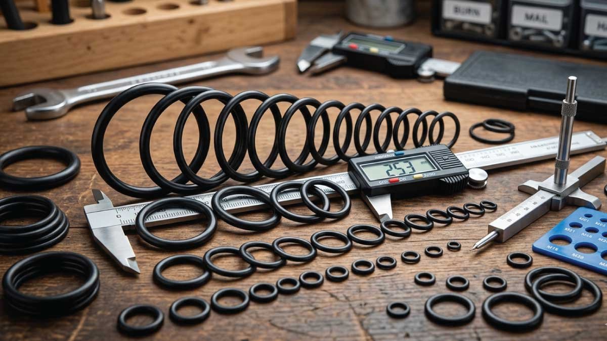
How to Measure an O-Ring
Measuring an O-ring correctly is important for selecting the right replacement and ensuring proper sealing performance. Even without a size chart, you can determine accurate dimensions using simple tools like a vernier caliper. Correct measurement helps prevent leakage, fitting issues, and early seal failure in mechanical and hydraulic systems.
Step 1: Measure Inner Diameter
The first step is to measure the inner diameter of the O-ring. Use a caliper and measure from one inner edge directly across to the opposite inner edge. Make sure the O-ring is not stretched during measurement, as this can affect accuracy and lead to incorrect sizing.
Step 2: Measure Cross Section
Next, measure the cross-sectional thickness of the O-ring. This is the circular thickness of the rubber ring. You can gently press it or measure it carefully with a caliper. This measurement is important because it determines how tightly the O-ring will seal under pressure in applications.
Step 3: Match with standard chart
After taking both measurements, compare them with standard ISO or metric O-ring size charts. This helps you find the exact matching size for replacement or design use. Matching ensures proper fit, effective sealing, and prevents leakage or mechanical failure in the system.
You May Also Like:
O-Ring Groove Design Basics
Proper groove design is essential for ensuring that an O-ring performs effectively under pressure and maintains a reliable seal. The groove holds the O-ring in place and controls how it deforms during compression. Even a correctly sized O-ring can fail if the groove dimensions are not designed properly.
Key groove parameters:
- Groove diameter
- Groove depth
- Groove width
If the groove is incorrect, even the right O-ring will fail because improper space or alignment can lead to leakage, extrusion, or uneven compression during operation.
Compression Ratio of O-Rings
Compression refers to how much the O-ring is squeezed between two mating surfaces when installed in a groove. This controlled deformation is what creates the sealing effect by filling gaps and preventing fluid or gas leakage.
Typical compression:
- Static seals: 15%–30%
- Dynamic seals: 10%–20%
Too much compression → damage
Too little compression → leakage
O-Ring Applications in Industry
O-rings are widely used sealing components in many industries because they are simple, cost-effective, and highly efficient in preventing leaks. They work by creating a tight seal between two surfaces, making them essential in systems that handle fluids, gases, pressure, and movement under different operating conditions.
1. Automotive systems
In automotive systems, O-rings are used in engines, fuel injectors, brake systems, and air conditioning units. They help prevent leakage of oil, fuel, and refrigerants while maintaining pressure integrity. Their durability and heat resistance make them essential for ensuring safe and efficient vehicle performance under varying operating conditions.
2. Hydraulic systems
In hydraulic systems, O-rings are used in cylinders, pumps, valves, and high-pressure systems. They provide a strong seal to prevent fluid leakage and maintain system pressure. This ensures smooth operation, energy efficiency, and reliable force transmission in heavy-duty applications such as construction machinery and industrial hydraulic equipment.
3. Pneumatic systems
In pneumatic systems, O-rings are commonly used in air compressors, pneumatic tools, and control valves. They help maintain airtight sealing, ensuring proper air pressure and efficient operation. These seals are important for reducing air leakage, improving tool performance, and ensuring smooth functioning of automation and industrial air-powered systems.
4. Industrial machinery
In industrial machinery, O-rings are used in heavy equipment, manufacturing machines, and press systems. They help prevent leakage of fluids and gases while withstanding high pressure and continuous operation. Their reliability and durability make them essential for maintaining efficiency, reducing downtime, and ensuring long-term performance in industrial environments.
You May Also Like:
Common O-Ring Size Mistakes
O-rings may look simple, but incorrect selection or installation can easily lead to leakage, system failure, or reduced service life. Many problems occur due to small measurement or material errors. Understanding these common mistakes helps ensure proper sealing performance in automotive, hydraulic, pneumatic, and industrial applications.
1. Using incorrect diameter
Using the wrong inner diameter is one of the most common mistakes. Even a small difference of 1 mm can prevent proper sealing, leading to leaks or pressure loss. Correct sizing is essential to ensure the O-ring fits tightly in the groove and performs its sealing function effectively.
2. Ignoring material compatibility
Different O-ring materials react differently to oils, chemicals, heat, and pressure. Using an incompatible material can cause swelling, cracking, or rapid degradation. Selecting the right material based on working conditions is important for durability, reliability, and long-term sealing performance in industrial and mechanical systems.
3. Over-compression
Over-compression happens when the O-ring is squeezed too tightly in the groove. This reduces elasticity and increases wear, leading to early failure. Proper compression ensures a balance between tight sealing and flexibility, allowing the O-ring to maintain performance without being damaged during continuous operation.
4. Reusing old O-rings
Reusing old O-rings is a common but risky practice. Over time, O-rings lose elasticity and develop cracks or deformation. Reinstalling them can lead to immediate leakage or system failure. Always replace old seals with new ones to ensure proper sealing and reliable system performance.
Tips for Choosing the Right M O-Ring Size
Selecting the correct O-ring size is essential for achieving proper sealing, preventing leaks, and ensuring system efficiency. A careful approach based on groove design, pressure, temperature, and standard sizing helps improve performance and extend service life in different mechanical and industrial applications.
1. Always check groove dimensions first
Never select an O-ring before measuring the groove. Groove dimensions determine the correct inner diameter and cross-section. Accurate measurement ensures proper fit, prevents leakage, and avoids installation issues. This step is essential for achieving reliable sealing performance in both low-pressure and high-pressure applications.
2. Consider pressure conditions
Operating pressure directly affects O-ring selection. High-pressure systems require thicker cross-sections to prevent extrusion and failure. Lower-pressure systems can use standard sizes. Understanding pressure conditions helps ensure the O-ring maintains sealing integrity without deformation or damage during continuous operation in mechanical systems.
3. Check temperature range
Temperature plays a major role in O-ring performance. Different materials react differently to heat and cold conditions. High temperatures may cause softening, while low temperatures may reduce flexibility. Choosing a material that matches the operating temperature ensures durability, flexibility, and long-lasting sealing performance.
4. Use standard ISO sizes
Using standard ISO or metric sizes is recommended for most applications. Standard sizes are widely available, cost-effective, and reliable. Custom sizes should only be used when absolutely necessary. This approach ensures easier replacement, better compatibility, and consistent sealing performance across industrial and mechanical systems.
Example
Let’s say you are repairing a hydraulic cylinder where proper sealing is critical to prevent fluid leakage and maintain system pressure. In such cases, selecting the correct O-ring size and material becomes very important for safe and efficient operation.
Requirements:
Shaft diameter: 25 mm
Groove design: standard hydraulic seal
Pressure: medium-high
Solution:
O-ring size: 25 mm ID × 2.5 mm CS
Material: NBR or Viton
Standard ISO metric series
This combination ensures proper fit inside the groove, reliable compression under pressure, and long service life even in demanding hydraulic conditions.
Final Thoughts
The M O-ring size (metric O-ring dimension chart) is an essential reference for engineers, mechanics, and technicians working in hydraulic, pneumatic, automotive, and industrial sealing systems. It helps ensure accurate selection and prevents costly mechanical failures.
The most important points to remember are:
- O-rings are defined by ID (inner diameter) and CS (cross-section)
- Even small size errors can cause leakage
- Material selection is as important as size
- ISO standard sizes ensure compatibility
In most applications, common O-ring sizes range from 5 mm to 100 mm inner diameter with cross-sections between 1.0 mm and 6.0 mm.
If you regularly work with sealing systems, keeping a metric O-ring size chart in your workshop or toolbox will save time, reduce errors, and improve overall system reliability.