
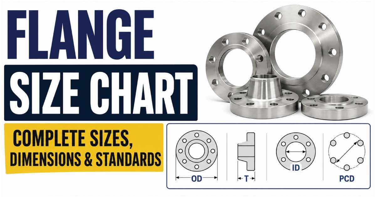
A flange size chart is an important reference for identifying flange dimensions, nominal pipe size, flange outside diameter, bolt circle diameter, bolt hole diameter, number of bolt holes, flange thickness, and bore diameter. Flanges are widely used in piping, plumbing, water treatment, oil and gas, chemical processing, HVAC, power generation, and industrial systems.
Choosing the correct flange requires more than knowing the pipe size. A flange may have the same nominal pipe size but different dimensions depending on its pressure class, standard, facing type, and flange design. For example, a 4-inch flange manufactured to one pressure class can have different outside diameter, bolt-hole dimensions, and thickness than a 4-inch flange from another class.
This comprehensive guide explains flange sizes, flange dimensions, ANSI flange sizes, ASME flange classes, metric flange sizes, bolt circle diameter, flange thickness, bore diameter, raised face dimensions, and common flange types.
What Is a Flange?
A flange is a mechanical component used to connect pipes, valves, pumps, equipment, and other piping components. Flanges normally use bolts, nuts, and a gasket to create a detachable and sealed connection.
A typical flanged connection consists of:
- Two mating flanges
- Bolts
- Nuts
- A gasket
- Connected pipe or equipment
The flange provides a strong connection while allowing the piping system to be disassembled for inspection, cleaning, maintenance, or replacement.
Flanges are manufactured in different sizes, pressure classes, materials, and configurations. Therefore, a flange size chart is useful for quickly comparing the dimensions of different flange specifications.
Flange Size Chart
The following table provides common dimensions for ASME B16.5 Class 150 raised-face steel flanges. Values are general reference dimensions and should be verified against the applicable standard for fabrication or critical applications.
| Nominal Size | NPS | Approx. Flange OD | Approx. Bolt Circle | Bolt Hole Diameter | No. of Bolts |
|---|---|---|---|---|---|
| 1/2 in | 0.5 | 3.50 in | 2.38 in | 0.62 in | 4 |
| 3/4 in | 0.75 | 3.88 in | 2.75 in | 0.62 in | 4 |
| 1 in | 1 | 4.25 in | 3.13 in | 0.62 in | 4 |
| 1-1/4 in | 1.25 | 4.63 in | 3.50 in | 0.62 in | 4 |
| 1-1/2 in | 1.5 | 5.00 in | 3.88 in | 0.62 in | 4 |
| 2 in | 2 | 6.00 in | 4.75 in | 0.75 in | 4 |
| 2-1/2 in | 2.5 | 7.00 in | 5.50 in | 0.75 in | 4 |
| 3 in | 3 | 7.50 in | 6.00 in | 0.75 in | 4 |
| 4 in | 4 | 9.00 in | 7.50 in | 0.75 in | 8 |
| 5 in | 5 | 10.00 in | 8.50 in | 0.88 in | 8 |
| 6 in | 6 | 11.00 in | 9.50 in | 0.88 in | 8 |
| 8 in | 8 | 13.50 in | 11.75 in | 0.88 in | 8 |
| 10 in | 10 | 16.00 in | 14.25 in | 1.00 in | 12 |
| 12 in | 12 | 19.00 in | 17.00 in | 1.00 in | 12 |
| 14 in | 14 | 21.00 in | 18.75 in | 1.13 in | 12 |
| 16 in | 16 | 23.50 in | 21.25 in | 1.13 in | 16 |
| 18 in | 18 | 25.00 in | 22.75 in | 1.25 in | 16 |
| 20 in | 20 | 27.50 in | 25.00 in | 1.25 in | 20 |
| 24 in | 24 | 32.00 in | 29.50 in | 1.25 in | 20 |
These dimensions represent common Class 150 flange dimensions. Different pressure classes and standards can have substantially different dimensions.
What Does Flange Size Mean?
Flange size normally refers to the nominal pipe size (NPS) that the flange is designed to connect.
For example:
- 1-inch flange → designed for 1-inch NPS piping
- 2-inch flange → designed for 2-inch NPS piping
- 4-inch flange → designed for 4-inch NPS piping
- 6-inch flange → designed for 6-inch NPS piping
- 12-inch flange → designed for 12-inch NPS piping
However, the flange itself will normally be considerably larger than the nominal pipe diameter.
For example, a 4-inch Class 150 flange has an outside diameter of approximately 9 inches.
This difference occurs because the flange must provide enough material for the bolt holes, gasket surface, pressure containment, and mechanical strength.
Main Flange Dimensions
A flange size chart can contain several important measurements.
Flange Outside Diameter
The outside diameter (OD) is the maximum diameter of the flange.
It is important when determining:
- Available installation space
- Clearance
- Pipe support arrangements
- Equipment connections
- Storage and handling requirements
Bolt Circle Diameter
The bolt circle diameter (BCD), also called the pitch circle diameter (PCD), is the diameter of the imaginary circle passing through the centers of the flange bolt holes.
The bolt circle is one of the most important flange dimensions because it determines whether two flanges can be bolted together.
Bolt Hole Diameter
Bolt hole diameter is the diameter of each hole through which the flange bolts pass.
The hole must provide adequate clearance for the specified bolt size.
Number of Bolt Holes
Flanges can have different numbers of bolt holes depending on their size, pressure class, and standard.
Flange Thickness
Thickness is measured through the main flange body.
Higher pressure classes often require greater flange dimensions and thickness.
Bore Diameter
The bore is the internal opening of the flange.
It must be compatible with the pipe or equipment connection.
Flange Class Explained
Flanges are commonly categorized according to pressure-temperature ratings.
Common ASME flange classes include:
- Class 150
- Class 300
- Class 400
- Class 600
- Class 900
- Class 1500
- Class 2500
The class number is not simply the maximum allowable pressure in psi.
The actual pressure rating depends on factors such as:
- Material
- Operating temperature
- Flange standard
- Construction
- Fluid
- Applicable pressure-temperature tables
Therefore, a Class 300 flange should not automatically be interpreted as a flange rated for exactly 300 psi under all conditions.
Class 150 Flange Size Chart
Class 150 is one of the most commonly encountered ASME flange classes.
| NPS | Typical Outside Diameter | Typical Bolt Count |
|---|---|---|
| 1/2 | 3.50 in | 4 |
| 3/4 | 3.88 in | 4 |
| 1 | 4.25 in | 4 |
| 1-1/4 | 4.63 in | 4 |
| 1-1/2 | 5.00 in | 4 |
| 2 | 6.00 in | 4 |
| 2-1/2 | 7.00 in | 4 |
| 3 | 7.50 in | 4 |
| 4 | 9.00 in | 8 |
| 6 | 11.00 in | 8 |
| 8 | 13.50 in | 8 |
| 10 | 16.00 in | 12 |
| 12 | 19.00 in | 12 |
| 14 | 21.00 in | 12 |
| 16 | 23.50 in | 16 |
| 18 | 25.00 in | 16 |
| 20 | 27.50 in | 20 |
| 24 | 32.00 in | 20 |
Exact dimensions should be checked against the applicable ASME standard and flange facing configuration.
Class 300 Flange Dimensions
Class 300 flanges generally have greater dimensions than Class 150 flanges for the same nominal pipe size.
For example, a 4-inch Class 300 flange is typically larger and heavier than a 4-inch Class 150 flange.
This difference can include:
- Larger outside diameter
- Larger bolt circle
- Larger or different bolt holes
- More or larger bolts
- Greater thickness
- Different raised-face dimensions
The exact dimensions depend on the flange type and applicable standard.
Class 600 Flange Dimensions
Class 600 flanges are designed for higher pressure-temperature service than lower classes when used with appropriate materials and conditions.
They are commonly encountered in:
- Oil and gas
- Petrochemical systems
- Power generation
- Industrial processing
- High-pressure piping
Class 600 flange dimensions should always be selected using the correct standard and material rating.
Metric Flange Size Chart
Metric piping systems commonly use DN nominal sizes.
| DN Size | Approx. NPS Equivalent |
|---|---|
| DN15 | 1/2 in |
| DN20 | 3/4 in |
| DN25 | 1 in |
| DN32 | 1-1/4 in |
| DN40 | 1-1/2 in |
| DN50 | 2 in |
| DN65 | 2-1/2 in |
| DN80 | 3 in |
| DN100 | 4 in |
| DN125 | 5 in |
| DN150 | 6 in |
| DN200 | 8 in |
| DN250 | 10 in |
| DN300 | 12 in |
| DN350 | 14 in |
| DN400 | 16 in |
| DN450 | 18 in |
| DN500 | 20 in |
| DN600 | 24 in |
DN and NPS are nominal designations and should not be treated as exact diameter conversions.
What Is a Flange Bolt Pattern?
The flange bolt pattern describes the arrangement of bolt holes around the flange.
The bolt pattern is determined by:
- Number of bolt holes
- Bolt circle diameter
- Bolt hole diameter
- Bolt size
- Flange standard
- Pressure class
For two flanges to connect correctly, their bolt patterns must be compatible.
A flange with the correct nominal pipe size can still fail to mate if its bolt circle or hole arrangement is different.
Flange Bolt Hole Chart
A typical flange bolt-hole specification includes the number of bolts and bolt-hole diameter.
| Flange Size | Typical Bolt Count | Typical Bolt Hole |
|---|---|---|
| 1/2 in | 4 | 5/8 in |
| 3/4 in | 4 | 5/8 in |
| 1 in | 4 | 5/8 in |
| 1-1/4 in | 4 | 5/8 in |
| 1-1/2 in | 4 | 5/8 in |
| 2 in | 4 | 3/4 in |
| 2-1/2 in | 4 | 3/4 in |
| 3 in | 4 | 3/4 in |
| 4 in | 8 | 3/4 in |
| 6 in | 8 | 7/8 in |
| 8 in | 8 | 7/8 in |
| 10 in | 12 | 1 in |
| 12 in | 12 | 1 in |
These values are representative of common Class 150 flange configurations.
Also Read: Journal Bearing Size Chart: Complete Guide 2026 + PDF
What Is a Raised Face Flange?
A raised face (RF) flange has a raised sealing surface around the pipe opening.
The gasket is positioned between the raised faces of two mating flanges.
Raised-face flanges are widely used in industrial piping because the raised surface concentrates the compressive force on the gasket.
Important raised-face dimensions include:
- Raised face diameter
- Raised face height
- Flange thickness
- Bore
- Outside diameter
- Bolt circle
The exact dimensions depend on the applicable flange standard and pressure class.
Flat Face Flange
A flat face (FF) flange has a flat gasket-bearing surface rather than a raised sealing face.
Flat-face flanges may be used with certain piping materials and equipment where a flat mating surface is required.
When connecting different flange types, the gasket and bolting arrangement must be appropriate for the application.
Ring-Type Joint Flange
A ring-type joint (RTJ) flange uses a specially machined groove designed to receive a metallic ring gasket.
RTJ flanges are commonly associated with high-pressure and high-temperature applications.
They require precise matching of:
- Flange size
- Pressure class
- RTJ groove
- Ring gasket type
- Bore
- Bolt pattern
An RTJ flange should not be treated as interchangeable with an ordinary raised-face flange.
Common Types of Flanges
Different flange designs serve different installation requirements.
Weld Neck Flange
A weld neck flange has a long tapered hub and is welded directly to the pipe.
It is frequently used in demanding piping systems.
Slip-On Flange
A slip-on flange slides over the pipe and is typically welded in position.
It is commonly used in general-purpose piping.
Blind Flange
A blind flange has no central bore.
It is used to close the end of a piping system, nozzle, or equipment connection.
Socket Weld Flange
A socket weld flange has a socket into which the pipe is inserted before welding.
It is commonly used with smaller pipe sizes.
Threaded Flange
A threaded flange has internal threads and can connect to threaded pipe without welding.
It may be useful in certain installations where welding is undesirable.
Lap Joint Flange
A lap joint flange is used with a separate stub end.
It can be useful where frequent disassembly is required.
Orifice Flange
An orifice flange is designed for use with an orifice plate assembly for flow measurement.
Also Read: Bushings Size Chart: Complete Guide 2026 With PDF
Flange Thickness Chart
Flange thickness varies depending on:
- Nominal size
- Pressure class
- Flange type
- Material
- Standard
- Facing
As pressure class increases, flange dimensions generally become more substantial.
However, there is no universal thickness that applies to every flange size.
For accurate flange thickness, use the applicable dimensional standard rather than a generalized chart.
How to Measure a Flange
If you have an unidentified flange, several measurements can help identify it.
Measure the Outside Diameter
Use a measuring tape or caliper to determine the maximum flange diameter.
Measure the Bolt Circle
Measure from the center of one bolt hole to the center of the opposite hole when possible. For some bolt patterns, a calculation or careful measurement between holes may be necessary.
Count the Bolt Holes
Count every bolt hole around the flange.
Measure the Bolt Hole Diameter
Measure the diameter of the bolt holes.
Measure the Bore
Measure the internal opening.
Measure Flange Thickness
Measure the main flange body thickness.
Check the Facing
Determine whether the flange is:
- Flat face
- Raised face
- Ring-type joint
- Another specialized configuration
These measurements can help narrow down the flange specification.
Also Read: How to Remove a Stripped Screw: 5-Step Guide
How to Identify an Unknown Flange
A reliable identification process should combine several dimensions rather than relying on one measurement.
Start with the nominal pipe size if known.
Then record:
- Outside diameter
- Bolt circle diameter
- Number of bolt holes
- Bolt-hole diameter
- Bore diameter
- Flange thickness
- Facing type
- Flange material
- Pressure class
- Markings or manufacturer’s identification
If the flange has markings stamped on it, those markings may identify the size, material, pressure class, and applicable standard.
Flange Size vs Pipe Size
A common mistake is assuming that the flange outside diameter should match the pipe outside diameter.
It does not.
For example, a nominal 4-inch pipe has an outside diameter of approximately 4.5 inches under common NPS steel pipe dimensions.
A corresponding Class 150 flange has an outside diameter of approximately 9 inches.
The flange is larger because it needs enough material for the gasket surface and bolting arrangement.
Therefore:
Pipe nominal size ≠ flange outside diameter
Instead, the flange is specified to match the nominal pipe size while having its own standardized dimensions.
How to Match Two Flanges
Two flanges should be matched based on their complete specifications.
Check:
- Nominal size
- Pressure class
- Flange standard
- Facing type
- Bolt circle
- Number of bolt holes
- Bolt-hole diameter
- Bore
- Material compatibility
- Gasket requirements
For example, two 4-inch flanges are not necessarily interchangeable simply because they are both labeled 4 inches.
A 4-inch Class 150 flange and a 4-inch Class 600 flange have different dimensions and should not be assumed to mate directly.
Flange Standards
Several standards are used to specify flange dimensions and performance.
ASME B16.5
ASME B16.5 is widely used for pipe flanges and flanged fittings in common nominal size ranges.
ASME B16.47
ASME B16.47 addresses larger-diameter steel flanges.
EN Standards
European flange systems commonly use EN standards and PN pressure designations.
DIN Standards
DIN standards are frequently encountered in European and international industrial equipment.
JIS Standards
Japanese Industrial Standards are used in many Japanese and Asian piping systems.
Because different standards can have different bolt patterns and dimensions, the flange standard is essential when identifying compatibility.
ANSI Flange Size Chart
The term ANSI flange is still commonly used in industry, although modern dimensional specifications are generally referenced through ASME standards.
Commonly encountered pressure classes include:
- ANSI/ASME Class 150
- ANSI/ASME Class 300
- ANSI/ASME Class 600
- ANSI/ASME Class 900
- ANSI/ASME Class 1500
- ANSI/ASME Class 2500
When searching for an “ANSI flange size chart,” users are generally looking for dimensions associated with these ASME flange classes.
PN Flange Size
European and many international flange systems commonly use PN pressure designations.
Examples include:
- PN6
- PN10
- PN16
- PN25
- PN40
- PN63
- PN100
- PN160
- PN250
- PN400
PN designations are nominal pressure classifications and should not simply be converted directly into psi without considering the relevant standard, material, and temperature.
Flange Material
Flanges are manufactured from various materials.
Carbon Steel Flanges
Carbon steel is widely used in general industrial and piping applications.
Stainless Steel Flanges
Stainless steel provides corrosion resistance and is commonly used in chemical, food, pharmaceutical, and marine environments.
Alloy Steel Flanges
Alloy steel may be selected for demanding temperature, pressure, or mechanical applications.
Cast Iron Flanges
Cast iron is used in certain water, drainage, and mechanical applications.
Ductile Iron Flanges
Ductile iron provides different mechanical characteristics and is commonly used in water and utility systems.
Material selection should match the piping system, fluid, temperature, pressure, and applicable code.
Common Flange Size Mistakes
Mistake 1: Matching Only the Pipe Size
Two flanges with the same nominal pipe size may have different pressure classes and bolt patterns.
Mistake 2: Ignoring the Flange Standard
ASME, EN, DIN, JIS, and other systems can have different dimensions.
Mistake 3: Confusing Pressure Class With Pressure Rating
A Class 300 flange is not automatically rated for 300 psi under every operating condition.
Mistake 4: Using the Wrong Gasket
The gasket must match the flange facing, dimensions, pressure, temperature, and service conditions.
Mistake 5: Ignoring Bolt Pattern
A flange cannot be correctly connected if the bolt-hole pattern does not match the mating flange.
Mistake 6: Assuming All 4-Inch Flanges Are Identical
A 4-inch flange can have different dimensions depending on class, standard, type, and facing.
Flange Size Chart in Millimeters
For users working with metric measurements, common Class 150 flange outside diameters can be converted approximately into millimeters.
| NPS | Flange OD | Approx. OD in mm |
|---|---|---|
| 1/2 in | 3.50 in | 88.9 mm |
| 3/4 in | 3.88 in | 98.6 mm |
| 1 in | 4.25 in | 108.0 mm |
| 1-1/4 in | 4.63 in | 117.6 mm |
| 1-1/2 in | 5.00 in | 127.0 mm |
| 2 in | 6.00 in | 152.4 mm |
| 2-1/2 in | 7.00 in | 177.8 mm |
| 3 in | 7.50 in | 190.5 mm |
| 4 in | 9.00 in | 228.6 mm |
| 6 in | 11.00 in | 279.4 mm |
| 8 in | 13.50 in | 342.9 mm |
| 10 in | 16.00 in | 406.4 mm |
| 12 in | 19.00 in | 482.6 mm |
| 14 in | 21.00 in | 533.4 mm |
| 16 in | 23.50 in | 596.9 mm |
| 18 in | 25.00 in | 635.0 mm |
| 20 in | 27.50 in | 698.5 mm |
| 24 in | 32.00 in | 812.8 mm |
Frequently Asked Questions About Flange Sizes
What is a flange size chart?
A flange size chart provides reference dimensions such as nominal pipe size, outside diameter, bolt circle diameter, bolt-hole diameter, number of bolts, bore, and thickness.
What is the most common flange class?
Class 150 is one of the most commonly encountered ASME flange classes, particularly in general industrial piping.
What does a 4-inch flange mean?
A 4-inch flange is designed around a nominal 4-inch pipe size. Its actual outside diameter is considerably larger than 4 inches.
What is the outside diameter of a 4-inch Class 150 flange?
A common 4-inch Class 150 flange has an outside diameter of approximately 9 inches, or 228.6 mm.
What is a bolt circle diameter?
Bolt circle diameter is the diameter of the imaginary circle passing through the centers of the flange bolt holes.
How many bolts does a 4-inch Class 150 flange have?
A typical 4-inch Class 150 flange uses 8 bolt holes.
Are Class 150 and Class 300 flanges the same size?
No. Although they can have the same nominal pipe size, their dimensions, bolt patterns, thicknesses, and pressure-temperature ratings can differ.
What is an ANSI flange?
“ANSI flange” is a common industry term for flanges associated with dimensional and pressure-class systems historically related to ANSI standards and now commonly specified through ASME standards.
What is a raised face flange?
A raised face flange has a raised gasket-contacting surface that concentrates gasket compression over the sealing area.
What is a blind flange?
A blind flange is a solid flange without a central pipe opening. It is used to close a pipe, valve, vessel nozzle, or other piping connection.
What information is needed to identify a flange?
The most useful information includes nominal size, pressure class, outside diameter, bolt circle, bolt-hole count, bolt-hole diameter, bore, thickness, facing type, and standard.
Final Thoughts on Flange Sizes
A flange size chart provides a quick way to understand the dimensions and specifications required for a reliable flanged piping connection. However, flange selection involves considerably more than nominal pipe size.
The most important dimensions include flange outside diameter, bolt circle diameter, bolt-hole diameter, number of bolt holes, bore diameter, flange thickness, and raised-face dimensions. The flange’s pressure class and manufacturing standard are equally important.
Common ASME flange classes include Class 150, 300, 600, 900, 1500, and 2500, while international systems may use PN pressure designations and standards such as EN, DIN, and JIS.
When selecting or replacing a flange, always verify:
- Nominal pipe size
- NPS or DN designation
- Pressure class or PN rating
- Flange standard
- Flange type
- Facing type
- Outside diameter
- Bolt circle diameter
- Number of bolt holes
- Bolt-hole diameter
- Bore diameter
- Flange thickness
- Material
- Gasket requirements
- Bolt and nut requirements
For general reference, a flange dimensions chart can help identify common sizes and compare different flange configurations. For fabrication, pressure-containing systems, and safety-critical applications, always use the current applicable standard and manufacturer specifications rather than relying solely on a general-purpose chart.