
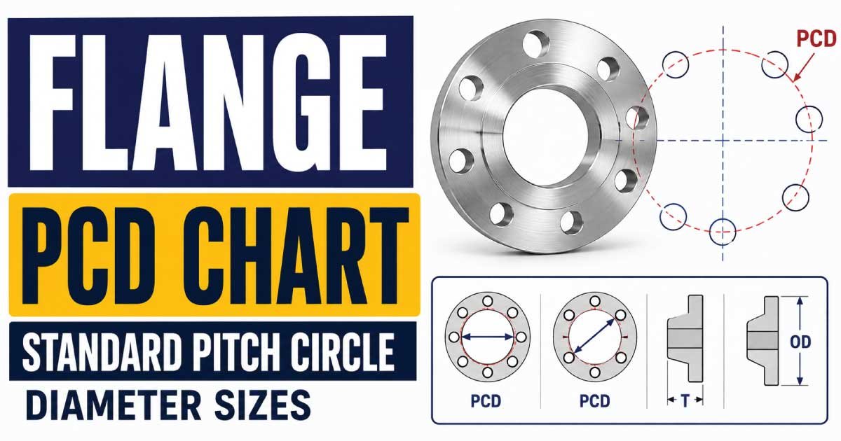
A flange PCD chart is used to identify the Pitch Circle Diameter (PCD) of pipe flanges. PCD is one of the most important flange dimensions because it determines the position of the bolt holes around the flange. It is also commonly called Bolt Circle Diameter (BCD).
When selecting, replacing, or identifying a flange, knowing the flange PCD is essential. Two flanges may have the same nominal pipe size but still have different PCDs because they belong to different pressure classes or standards.
This guide provides a practical flange PCD chart, explains how PCD is measured, covers common ASME/ANSI flange sizes, metric flange PCDs, bolt-hole patterns, and explains the difference between PCD, flange OD, and bore diameter.
What Is Flange PCD?
PCD stands for Pitch Circle Diameter.
On a flange, the PCD is the diameter of an imaginary circle that passes through the center points of all the bolt holes.
For example, if a flange has a PCD of 7.50 inches, the centers of its bolt holes are positioned around an imaginary circle with a diameter of 7.50 inches.
PCD is important because the mating flange must have a compatible bolt-hole pattern.
The basic flange dimensions include:
- Flange outside diameter
- PCD
- Bolt-hole diameter
- Number of bolt holes
- Bore diameter
- Flange thickness
- Facing dimensions
Among these measurements, PCD is especially useful for determining whether two flanges can be bolted together.
Flange PCD Chart
The following chart provides common ASME B16.5 Class 150 flange PCD values for general reference.
| Nominal Size | NPS | PCD / Bolt Circle Diameter |
|---|---|---|
| 1/2 inch | 1/2 | 2.38 in |
| 3/4 inch | 3/4 | 2.75 in |
| 1 inch | 1 | 3.13 in |
| 1-1/4 inch | 1-1/4 | 3.50 in |
| 1-1/2 inch | 1-1/2 | 3.88 in |
| 2 inch | 2 | 4.75 in |
| 2-1/2 inch | 2-1/2 | 5.50 in |
| 3 inch | 3 | 6.00 in |
| 4 inch | 4 | 7.50 in |
| 5 inch | 5 | 8.50 in |
| 6 inch | 6 | 9.50 in |
| 8 inch | 8 | 11.75 in |
| 10 inch | 10 | 14.25 in |
| 12 inch | 12 | 17.00 in |
| 14 inch | 14 | 18.75 in |
| 16 inch | 16 | 21.25 in |
| 18 inch | 18 | 22.75 in |
| 20 inch | 20 | 25.00 in |
| 24 inch | 24 | 29.50 in |
These values are representative of common Class 150 configurations. Always verify exact dimensions against the applicable standard before fabrication or installation.
Flange PCD Chart in Millimeters
For metric work, flange PCD is often measured in millimeters.
| NPS | PCD (inches) | PCD (mm) |
|---|---|---|
| 1/2 in | 2.38 | 60.3 mm |
| 3/4 in | 2.75 | 69.9 mm |
| 1 in | 3.13 | 79.4 mm |
| 1-1/4 in | 3.50 | 88.9 mm |
| 1-1/2 in | 3.88 | 98.6 mm |
| 2 in | 4.75 | 120.7 mm |
| 2-1/2 in | 5.50 | 139.7 mm |
| 3 in | 6.00 | 152.4 mm |
| 4 in | 7.50 | 190.5 mm |
| 5 in | 8.50 | 215.9 mm |
| 6 in | 9.50 | 241.3 mm |
| 8 in | 11.75 | 298.5 mm |
| 10 in | 14.25 | 362.0 mm |
| 12 in | 17.00 | 431.8 mm |
| 14 in | 18.75 | 476.3 mm |
| 16 in | 21.25 | 539.8 mm |
| 18 in | 22.75 | 577.9 mm |
| 20 in | 25.00 | 635.0 mm |
| 24 in | 29.50 | 749.3 mm |
The millimeter values are approximate conversions from the inch dimensions.
What Does PCD Mean on a Flange?
When a flange specification lists a PCD measurement, it tells you the diameter of the bolt-hole circle.
For example:
4-inch Class 150 flange
- Flange OD: approximately 9 inches
- PCD: approximately 7.5 inches
- Bolt holes: 8
- Bolt-hole diameter: approximately 0.75 inch
The PCD is therefore smaller than the outside diameter because the bolt holes are positioned inside the flange perimeter.
PCD vs Bolt Circle Diameter
In most flange applications, PCD and Bolt Circle Diameter (BCD) refer to the same basic measurement.
You may see:
- PCD
- Pitch Circle Diameter
- Bolt Circle Diameter
- BCD
- Bolt Circle
- Pitch Circle
These terms describe the circular pattern formed by the centers of the bolt holes.
The terminology can vary between manufacturers, industries, and standards.
How to Measure Flange PCD
Measuring PCD directly is easy when the flange has an accessible bolt-hole pattern.
Method 1: Opposite Bolt Holes
If the flange has an even number of equally spaced bolt holes, measure from the center of one bolt hole directly across to the center of the opposite bolt hole.
That measurement is the PCD.
For example:
Center-to-center measurement = 190.5 mm
Therefore:
PCD = 190.5 mm
Method 2: Measure Between Hole Edges
If measuring from the hole edges rather than the centers, use the appropriate calculation.
For opposite holes:
PCD = Distance between inner edges + Bolt-hole diameter
or
PCD = Distance between outer edges − Bolt-hole diameter
The correct formula depends on exactly where the measurement is taken.
Flange PCD Formula
For a flange with evenly spaced bolt holes, PCD can be determined from several measurements.
If you measure the distance between the centers of two directly opposite holes:
PCD = Center-to-center distance
If you measure the distance between the nearest edges of opposite holes:
PCD = Edge-to-edge distance + Hole diameter
If you measure from the outer edge of one hole to the outer edge of the opposite hole:
PCD = Outer-edge distance − Hole diameter
Accurate measurement is important when identifying an unknown flange.
4 Inch Flange PCD
One of the most commonly searched flange PCD dimensions is the 4-inch flange PCD.
For a typical ASME Class 150 flange:
4-inch flange PCD = approximately 7.50 inches
or:
190.5 mm
A typical 4-inch Class 150 flange also has:
- 9-inch outside diameter
- 7.5-inch PCD
- 8 bolt holes
- Approximately 0.75-inch bolt holes
However, these dimensions change with pressure class and standard.
6 Inch Flange PCD
For a common Class 150 flange:
6-inch flange PCD = approximately 9.50 inches
or:
241.3 mm
The flange typically has:
- 11-inch outside diameter
- 9.5-inch PCD
- 8 bolt holes
A 6-inch Class 300 flange does not necessarily have the same PCD.
8 Inch Flange PCD
For a common Class 150 configuration:
8-inch flange PCD = approximately 11.75 inches
or:
298.5 mm
The typical flange has:
- 13.5-inch outside diameter
- 11.75-inch PCD
- 8 bolt holes
10 Inch Flange PCD
A typical Class 150 10-inch flange has:
PCD = approximately 14.25 inches
or:
362.0 mm
It commonly uses:
- 16-inch outside diameter
- 14.25-inch PCD
- 12 bolt holes
12 Inch Flange PCD
A typical Class 150 12-inch flange has:
PCD = approximately 17 inches
or:
431.8 mm
Common dimensions include:
- 19-inch outside diameter
- 17-inch PCD
- 12 bolt holes
24 Inch Flange PCD
For a common Class 150 configuration:
24-inch flange PCD = approximately 29.50 inches
or:
749.3 mm
The flange outside diameter is approximately 32 inches.
Large flanges can have significantly different dimensions depending on whether they are manufactured under ASME B16.5 or large-diameter flange standards.
Also Read: Jet Engine Turbine Blade Size Chart With Guide
Flange PCD and Bolt Hole Pattern
PCD does not provide the complete bolt pattern by itself.
A complete bolt pattern normally requires:
- PCD
- Number of bolt holes
- Bolt-hole diameter
- Hole spacing
- Bolt size
For example:
190.5 mm PCD × 8 holes × 19.1 mm holes
describes much more information than PCD alone.
Two flanges can theoretically have the same PCD but different numbers or sizes of bolt holes.
Therefore, always check the complete bolt pattern.
Flange PCD Chart With Bolt Holes
| NPS | PCD | Approx. PCD mm | Bolt Holes |
|---|---|---|---|
| 1/2 | 2.38 in | 60.3 mm | 4 |
| 3/4 | 2.75 in | 69.9 mm | 4 |
| 1 | 3.13 in | 79.4 mm | 4 |
| 1-1/4 | 3.50 in | 88.9 mm | 4 |
| 1-1/2 | 3.88 in | 98.6 mm | 4 |
| 2 | 4.75 in | 120.7 mm | 4 |
| 2-1/2 | 5.50 in | 139.7 mm | 4 |
| 3 | 6.00 in | 152.4 mm | 4 |
| 4 | 7.50 in | 190.5 mm | 8 |
| 5 | 8.50 in | 215.9 mm | 8 |
| 6 | 9.50 in | 241.3 mm | 8 |
| 8 | 11.75 in | 298.5 mm | 8 |
| 10 | 14.25 in | 362.0 mm | 12 |
| 12 | 17.00 in | 431.8 mm | 12 |
| 14 | 18.75 in | 476.3 mm | 12 |
| 16 | 21.25 in | 539.8 mm | 16 |
| 18 | 22.75 in | 577.9 mm | 16 |
| 20 | 25.00 in | 635.0 mm | 20 |
| 24 | 29.50 in | 749.3 mm | 20 |
Does Flange PCD Change With Pressure Class?
Yes.
The PCD can change depending on the flange pressure class and applicable standard.
For example, a 4-inch flange manufactured to different pressure classes may have different:
- Outside diameter
- PCD
- Bolt-hole diameter
- Number of bolt holes
- Thickness
- Facing dimensions
This is why a flange should always be specified using its size and pressure class, not its nominal pipe size alone.
Class 150 Flange PCD
Class 150 is one of the most commonly used ASME flange classes.
Some representative PCD values include:
| NPS | Class 150 PCD |
|---|---|
| 2 in | 4.75 in |
| 3 in | 6.00 in |
| 4 in | 7.50 in |
| 6 in | 9.50 in |
| 8 in | 11.75 in |
| 10 in | 14.25 in |
| 12 in | 17.00 in |
| 16 in | 21.25 in |
| 20 in | 25.00 in |
| 24 in | 29.50 in |
These are useful reference values for common Class 150 flange configurations.
Also Read: Standard MDF board Size Chart With Guide
Class 300 Flange PCD
Class 300 flange PCD values differ from Class 150 values.
This is particularly important when replacing an existing flange.
For example, simply purchasing a flange labeled 4-inch is not enough. The supplier should know whether the required flange is:
- Class 150
- Class 300
- Class 600
- Another pressure class
The flange standard and facing should also be specified.
Metric Flange PCD
Metric flange systems commonly use DN sizes and standards such as EN or DIN.
Common DN sizes include:
- DN15
- DN20
- DN25
- DN32
- DN40
- DN50
- DN65
- DN80
- DN100
- DN125
- DN150
- DN200
- DN250
- DN300
- DN350
- DN400
- DN450
- DN500
- DN600
Metric flange PCD depends on the specific standard and pressure designation.
For example, DN100 PN16 and DN100 PN10 should not automatically be assumed to have identical PCD dimensions.
DIN Flange PCD
DIN flange PCD dimensions are commonly specified in millimeters.
The PCD depends on:
- DN size
- PN pressure designation
- Flange type
- Applicable DIN/EN standard
Common PN classes include:
- PN6
- PN10
- PN16
- PN25
- PN40
- PN63
- PN100
- PN160
When using a DIN or EN flange, always identify both the DN size and PN rating.
JIS Flange PCD
Japanese Industrial Standard flange systems use their own dimensional specifications.
A JIS flange can have a different bolt pattern from an ASME flange with a similar nominal size.
Therefore, an ASME flange and JIS flange should not be assumed to be interchangeable simply because their pipe sizes appear similar.
Also Read: Allen Key Size Chart: Complete Metric & Inch Guide
Flange PCD vs Flange OD
PCD and flange outside diameter are two different measurements.
Flange OD is the maximum outside diameter of the flange.
PCD is the diameter through the centers of the bolt holes.
For example, a typical 4-inch Class 150 flange has approximately:
- OD = 9 inches
- PCD = 7.5 inches
Therefore:
PCD < Flange OD
The difference between these measurements provides space around the bolt holes and the outer flange edge.
Flange PCD vs Bore Diameter
Bore diameter is the internal opening through the flange.
PCD is the bolt-hole circle.
They are completely different dimensions.
For example, a flange might have:
- 9-inch OD
- 7.5-inch PCD
- Approximately 4.0-inch nominal bore region
Therefore, bore size should never be confused with PCD.
How to Identify a Flange Using PCD
PCD can be particularly useful when you have an unidentified flange.
Record the following:
- Outside diameter
- PCD
- Number of holes
- Bolt-hole diameter
- Bore diameter
- Thickness
- Facing type
- Nominal pipe size
- Pressure class if available
For example, suppose you measure:
OD: 9 inches
PCD: 7.5 inches
Bolt holes: 8
Bolt-hole diameter: approximately 0.75 inch
This combination may indicate a common 4-inch Class 150 flange configuration.
However, identification should be confirmed using all available measurements and markings.
Also Read: How to Measure Pipe Diameter Easily with Size Chart
Why Flange PCD Is Important
Correct PCD is essential for flange connection.
If the PCD is wrong:
- Bolt holes will not align
- Bolts cannot be inserted correctly
- Flanges cannot be properly assembled
- Gasket alignment may be affected
- Installation can be delayed
In industrial piping systems, even a small dimensional mismatch can make a flange unusable.
This is why PCD should be checked carefully when ordering replacement flanges.
Common Flange PCD Mistakes
Mistake 1: Measuring Flange OD Instead of PCD
The outside diameter is measured at the outer edge. PCD is measured through the centers of the bolt holes.
Mistake 2: Measuring Hole Edge to Hole Edge
This does not directly provide PCD unless the bolt-hole diameter is included in the calculation.
Mistake 3: Ignoring Bolt Hole Count
PCD alone does not define the complete bolt pattern.
Mistake 4: Ignoring Pressure Class
Different pressure classes can use different PCDs.
Mistake 5: Assuming All Standards Match
ASME, DIN, EN, JIS, and other flange systems can have different bolt patterns.
Frequently Asked Questions About Flange PCD
What is PCD in a flange?
PCD means Pitch Circle Diameter. It is the diameter of the imaginary circle passing through the centers of the flange bolt holes.
Is PCD the same as bolt circle diameter?
Yes, in most flange applications, PCD and bolt circle diameter refer to the same basic dimension.
What is the PCD of a 4-inch Class 150 flange?
A typical 4-inch Class 150 flange has a PCD of approximately 7.50 inches or 190.5 mm.
What is the PCD of a 6-inch Class 150 flange?
A typical 6-inch Class 150 flange has a PCD of approximately 9.50 inches or 241.3 mm.
What is the PCD of an 8-inch Class 150 flange?
A typical 8-inch Class 150 flange has a PCD of approximately 11.75 inches or 298.5 mm.
What is the PCD of a 10-inch Class 150 flange?
A typical 10-inch Class 150 flange has a PCD of approximately 14.25 inches or 362.0 mm.
What is the PCD of a 12-inch Class 150 flange?
A typical 12-inch Class 150 flange has a PCD of approximately 17 inches or 431.8 mm.
How do I measure flange PCD?
For an even number of equally spaced bolt holes, measure from the center of one bolt hole to the center of the opposite bolt hole.
Does flange PCD depend on pressure class?
Yes. PCD can change depending on the pressure class, nominal size, and flange standard.
Can I match a flange using PCD alone?
No. PCD is important, but you should also check the number of bolt holes, bolt-hole diameter, flange OD, bore, thickness, facing, standard, and pressure class.
Final Flange PCD Reference
A flange PCD chart is an important reference for identifying and selecting pipe flanges. PCD, also called Pitch Circle Diameter or Bolt Circle Diameter, describes the circle passing through the centers of the flange bolt holes.
For common Class 150 configurations, some useful reference values are:
- 2-inch flange: 4.75-inch PCD
- 3-inch flange: 6.00-inch PCD
- 4-inch flange: 7.50-inch PCD
- 6-inch flange: 9.50-inch PCD
- 8-inch flange: 11.75-inch PCD
- 10-inch flange: 14.25-inch PCD
- 12-inch flange: 17.00-inch PCD
- 16-inch flange: 21.25-inch PCD
- 20-inch flange: 25.00-inch PCD
- 24-inch flange: 29.50-inch PCD
However, these values should be treated as reference dimensions, not a substitute for the applicable flange standard.
When selecting a flange, always verify NPS/DN size, pressure class, flange standard, PCD, bolt-hole diameter, number of holes, flange OD, bore, thickness, and facing type. This complete approach ensures that the flange and its mating component have a compatible dimensional and bolting pattern.